Load Cell Module DVP02LC-SL
DVP-PLC Operation Manual
27
y CH1 stable measured value: Corresponds to bit4 of CR#50. When the value measured at
CH1 is stable, the indicator will turn red.
y CH2 zero weight (empty): Corresponds to bit1 of CR#50. When the value measured at CH2
equals 0, the indicator will turn red.
y CH2 max. weight (overload): Corresponds to bit3 of CR#50. When the value measured at
CH2 exceeds the maximum weight set, the indicator will turn red.
y CH2 stable measured value: Corresponds to bit5 of CR#50. When the value measured at
CH2 is stable, the indicator will turn red.
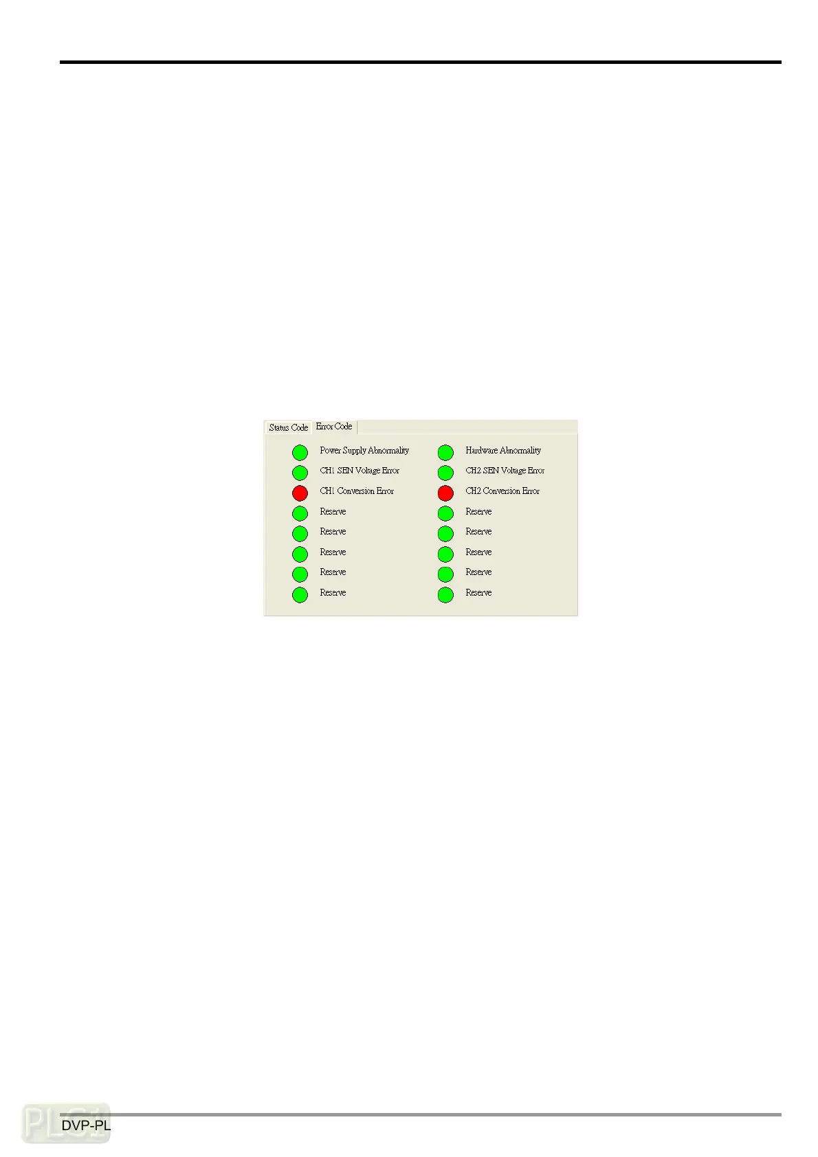
Error Code:
Corresponds to the value in CR#51, displaying the operation status of DVP02LC-SL, including
power supply abnormality, hardware abnormality, SEN voltage errors and conversion errors.
y Power supply abnormality: Corresponds to bit0 of CR#51. When the power supply for
DVP02LC-SL encounters abnormality, the indicator will turn red.
y Hardware abnormality: Corresponds to bit1 of CR#51. When the hardware of DVP02LC-SL
encounters abnormality, the indicator will turn red.
y CH1 SEN voltage error: Corresponds to bit3 of CR#51. When the SEN signal input at CH1
encounters error, i.e. abnormal load cell signal occurs, the indicator will turn red.
y CH2 SEN voltage error: Corresponds to bit5 of CR#51. When the SEN signal input at CH2
encounters error, i.e. abnormal load cell signal occurs, the indicator will turn red.
y CH1 conversion error: Corresponds to bit4 of CR#51. When the conversion of the measured
signal at CH1 encounters an error, the indicator will turn red.
y CH2 conversion error: Corresponds to bit6 of CR#51. When the conversion of the measured
signal at CH2 encounters an error, the indicator will turn red.

 Loading...