Load Cell Module DVP02LC-SL
DVP-PLC Operation Manual
5
Example: If you use a load cell of eigenvalue 3.8 mV/V, please set CR#2 to “2” to acquire the best
ENOB. When CR#3 is set to “2 ms”, the ENOB will be 19 bits. When CR#3 is set to “20 ms”, the
ENOB will be 20.5 bits.
* For explanations on CR#2 and CR#3, see 5.2.
3 Product Profile and Outline
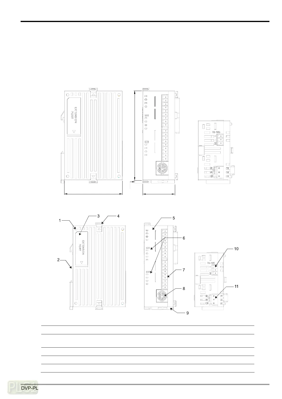
3.1 Dimensions
3 mm
90 mm
33 mm
60 mm
CH2
CH1
DVP02LC
MAX
MOTION
MAX
NET
ZERO
MOTION
ERROR
ZERO
NET
L.V
POWER
RUN
SHD
SEN+
EXC+
SIG+
SEN-
SIG-
EXC-
SEN+
SEN-
SHD
SIG-
SIG+
EXC+
EXC-
3.2 Product Profiles
CH2
CH1
DVP02LC
MAX
MOTION
MAX
NET
ZERO
MOTION
ERROR
ZERO
NET
L.V
POWER
RUN
SHD
SEN+
EXC+
SIG+
SEN-
SIG-
EXC-
SEN+
SEN-
SHD
SIG-
SIG+
EXC+
EXC-
1. Mounting hole for the I/O module 2. DIN rail slot (35mm)
3. I/O module connection port 4. I/O module clip
5.
Status indicators (POWER, RUN,
ERROR, L.V)
6.
Function status indicators (NET,
ZERO, MAX, MOTION)
7. I/O terminals 8. RS-232 port
9. DIN rail clip 10. RS-485 port
11. DC power input

 Loading...