Load Cell Module DVP02LC-SL
DVP-PLC Operation Manual
6
3.3 Terminal Layout
DVP02LC-SL
SEN-SEN+SIG-SIG+EXC-EXC+ SIG+EXC-EXC+SHD SHDSEN-SEN+SIG-
CH1 CH2
3.4 LED Indicators
LED Color Function
POWER Green Indicating the power supply status.
RUN Green Indicating the operating status of DVP02LC-SL.
ERROR Red Indicating error statuses.
L.V Red Indicating low voltage from the external power supply.
NET Orange Indicating net/gross weights.
ZERO Orange Indicating the zero point weight.
MAX Orange Indicating the maximum weight.
MOTION Orange Indicating stable measurements.
4 Installation and Wiring
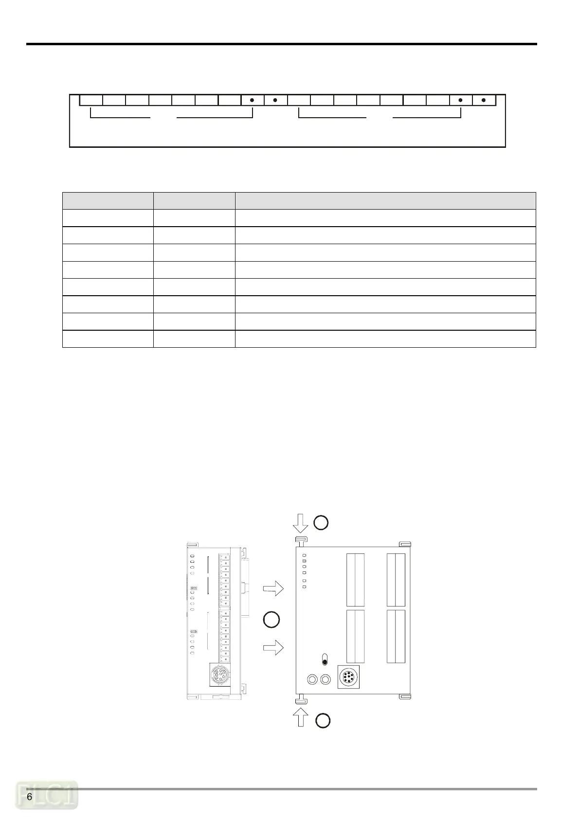
4.1 Connecting DVP02LC-SL to DVP-SV series PLC MPU
Open the fixing clips on the top and bottom at the left side of DVP-SV series PLC MPU. Meet
the connection ports alongside the 4 corners of DVP02LC-SL with DVP-SV, as step
①
.
Press the fixing clips on the top and bottom of the DVP-SV series PLC MPU and check if the
connection is tight enough, as step
②
.
DVP28SV
RUN
STOP
2
2
11
CH 2
CH 1
DVP02LC
MAX
MOT ION
MAX
NE T
ZERO
MOT ION
ERROR
ZERO
NE T
L. V
POWER
RU N
SHD
SEN+
EXC+
SIG+
SEN-
SIG-
EXC-
SEN+
SEN-
SHD
SIG-
SIG+
EXC+
EXC-

 Loading...