8
‘2’
‘0’ ‘2’
‘2’
‘1’
Number of data
(byte)
‘4’ ‘0’ ‘0’
‘1’ ‘0’
‘7’
‘0’ ‘0’
‘7’
Starting data
address
‘2’
Content of
starting data
address
2102H
‘0’
Data address
‘1’
Data address
‘1’
‘0’ ‘0’ ‘1’ ‘1’
‘0’ ‘0’ ‘7’ ‘7’
‘0’
‘0’ ‘7’
‘7’
Number of
data
(Count by
word)
‘2’
Content of data
address 2103H
‘0’
Data content
‘0’
Data content
‘0’
‘D’ ‘7’ “5’ ‘5’
LRC CHK 1
LRC CHK 0
‘7’
LRC CHK 1
LRC CHK 0
‘1’
LRC CHK 1
LRC CHK 0
‘1’
LRC CHK 1
LRC CHK 0
‘1’
CR
CR CR
CR
END 1
END 0
LF
END 1
END 0
LF
END 1
END 0
LF
END 1
END 0
LF
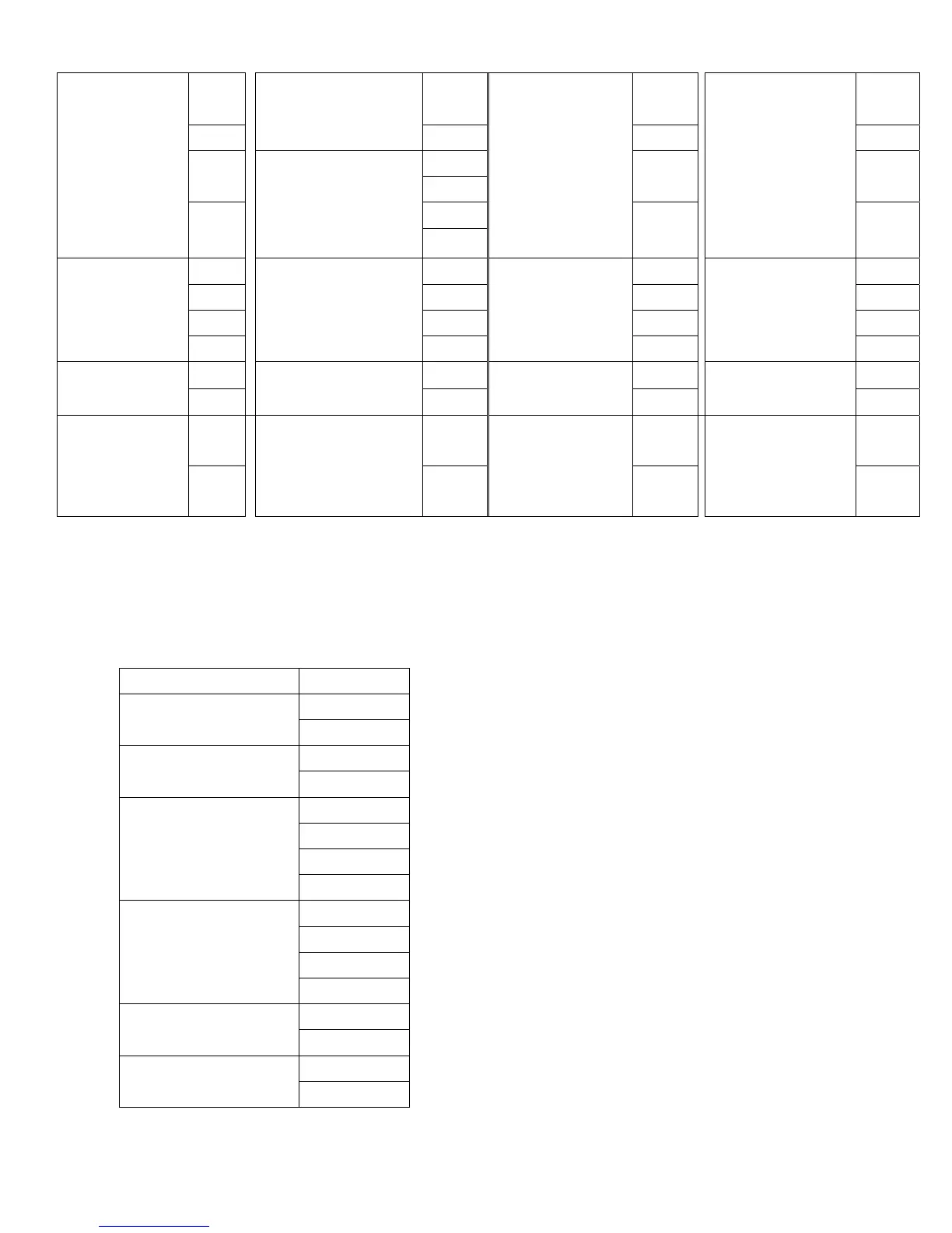
CHK (check sum)
LRC (Longitudinal Redundancy Check) is calculated by summing up the values of the
bytes from ADR1 to last data character then calculating the hexadecimal representation
of the 2’s-complement negation of the sum. For example, using the command message
of above:
STX ‘:’
‘0’ ADR 1
ADR 2
‘1’
‘0’ CMD 1
CMD 2
‘3’
‘2’
‘1’
‘0’
STARTING DATA
ADDRESS
‘2’
‘0’
‘0’
‘0’
NUMBER OF
DATA
‘2’
‘D’ LRC CHK 1
LRC CHK 0
‘7’
CR END 1
END 0
LF
01H+03H+21H+02H+00H+02H=29H, the
2’s-complement negation of 29H is D7H.