Chapter 12 Descriptions of Parameter SettingsC2000 Plus
12.1-02-23
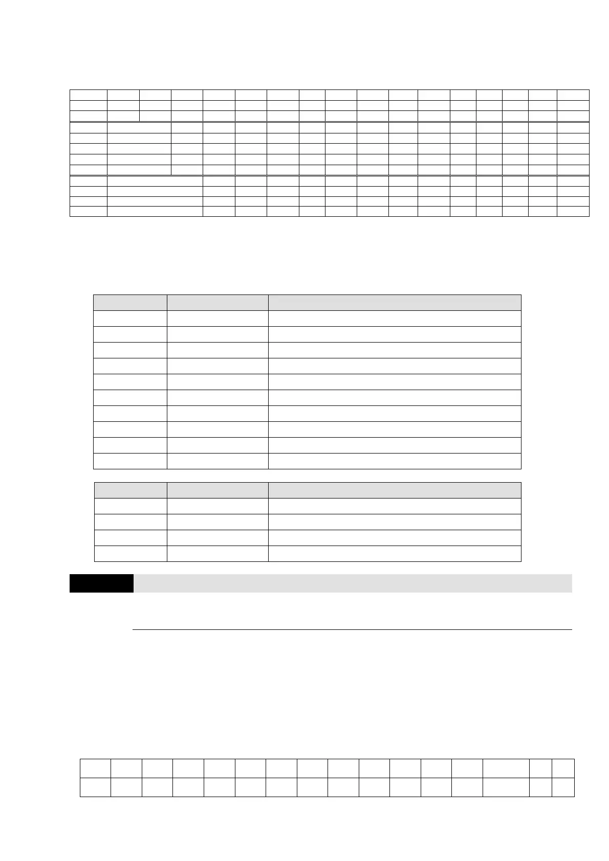
Add Remote IO function to directly control drive’s AO / DO and read current AI / DI status through
the standard Modbus, the corresponding indexes of 26xx are as following:
bit15 bit14 bit13 bit12 bit11 bit10 bit9 bit8 bit7
bit6 bit5 bit4 bit3 bit2 bit1 bit0
2600h MI15 MI14 MI13 MI12 MI11 MI10 MI8 MI7 MI6
MI5 MI4 MI3 MI2 MI1 REV FWD
2640h - - - - - MO15 MO14 MO13 MO12
MO11 MO10 MO2 MO1 - RY2 RY1
2660h AVI
- - - - - - - - - - - - - -
2661h ACI
- - - - - - - - - - - - - -
2662h AUI
- - - - - - - - - - - - - -
266Ah AI10
- - - - - - - - - - - - - -
266Bh AI11
- - - - - - - - - - - - - -
26A0h AFM1
- - - - - - - - - - - - -
26A1h AFM2
- - - - - - - - - - - - -
26AAh AO10
- - - - - - - - - - - - -
26ABh AO11
- - - - - - - - - - - - -
In addition, the AI and DI value can be read directly, while DO and AO must be controlled by
Modbus under corresponding parameter function. The related parameter definition is as
following:
DO
Terminal Pr. Setting Indexes of Modbus direct control
RY1 Pr.02-13 = 51 The bit0 of 2640h
RY2 Pr.02-14 = 51 The bit1 of 2640h
MO1 Pr.02-16 = 51 The bit3 of 2640h
MO2 Pr.02-17 = 51 The bit4 of 2640h
MO10 Pr.02-36 = 51 The bit5 of 2640h
MO11 Pr.02-37 = 51 The bit6 of 2640h
MO12 Pr.02-38 = 51 The bit7 of 2640h
MO13 Pr.02-39 = 51 The bit8 of 2640h
MO14 Pr.02-40 = 51 The bit9 of 2640h
MO15 Pr.02-41 = 51 The bit10 of 2640h
AO
Terminal Pr. Setting Indexes of Modbus direct control
AFM1 Pr.03-20=21 The value of 26A0h
AFM2 Pr.03-23=21 The value of 26A1h
AFM10 Pr.14-12=21 The value of 26AAh
AFM11 Pr.14-13=21 The value of 26ABh
02-18
Multi-Function Output Direction
Default: 0000h
Settings 0000h–FFFFh (0: N.O.; 1: N.C.)
This parameter is in hexadecimal.
This parameter is set by a bit. If a bit is 1, the corresponding multi-function output acts in an
opposite way.
Example: Assume Pr.02-13=1 (indication when the drive is operating). If the output is positive, the
bit is set to 0, and the Relay is ON when the drive runs and is OFF when the drive stops. On the
contrary, if the output is negative, and the bit is set to 1, then the Relay is OFF when the drive runs
and is ON when the drive stops.
bit15 bit14 bit13 bit12 bit11 bit10 bit9 bit8 bit7 bit6 bit5 bit4 bit3 bit2 bit1 bit0
MO20 MO19 MO18 MO17 MO16 MO15 MO14 MO13 MO12 MO11 MO10 MO2 MO1 Reserved RY2 RY1