Chapter 2. Wiring | VFD-VJ
2-15
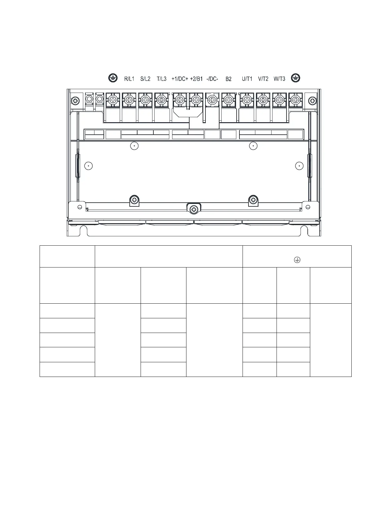
Specifications of the Main Circuit Terminals
VJ-A and VJ-C Air Cooled
Frame C
Main Circuit Terminals:
R/L1, S/L2, T/L3, U/T1, V/T2, W/T3, DC+, DC-, B1,
B2
Grounding Terminal:
Models
Max. Wire
Gauge
Mini. Wire
Gauge
Screw Size
and
Torque Force
(± 10%)
Max.
Wire
Gauge
Mini.
Wire
Gauge
Screw Size
and
Torque
Force
(± 10%)
VFD-110VL23A-J
16 mm
2
(6 AWG)
16 mm
2
(6 AWG)
M5
30 kg-cm
(26.0 lb-in)
(2.94 Nm)
16 mm
2
(6 AWG)
16 mm
2
(6 AWG)
M5
30 kg-cm
(26.0 lb-in.)
(2.94 Nm)
VFD110VL43C-J
10 mm
2
(8 AWG)
10 mm
2
(8 AWG)
10 mm
2
(8 AWG)
VFD150VL43C-J
10 mm
2
( 8 AWG)
10 mm
2
(8 AWG)
10 mm
2
(8 AWG)
VFD185VL43C-J
16 mm
2
(6 AWG)
16 mm
2
(6 AWG)
16 mm
2
(6 AWG)
VFD220VL43C-J
16 mm
2
(6 AWG)
16 mm
2
(6 AWG)
16 mm
2
(6 AWG)
NOTE:
1. If you install at Ta 45°C environment, select copper wire with voltage rating of 600 V and temperature
resistance of 75°C or 90°C
2. If you install at Ta 45°C above environment, select copper wire with voltage rating of 600 V and temperature
resistance of 90°C or above.
3. For UL installation compliance, use copper wires when installing. The wire gauge is based on a temperature
resistance of 75°C, in accordance with UL requirements and recommendations.
4. Do not reduce the wire gauge when using higher temperature wire.
 Loading...
