Chapter 14 Fault Codes and DescriptionsME300
14-20
Cause Corrective Actions
The upper unit does not transmit
the communication command
within Pr.09-03 setting time.
Check if the upper unit transmits the communication command within the setting
time for Pr.09-03.
Malfunction caused by interference
Verify the wiring and grounding of the communication circuit. It is recommended
to separate the communication circuit from the main circuit, or wire in 90 degree
for effective anti-interference performance.
Different communication setting
from the upper unit
Check if the setting for Pr.09-02 is the same as the setting for the upper unit.
Disconnection or bad connection
of the cable
Check the cable and replace it if necessary.
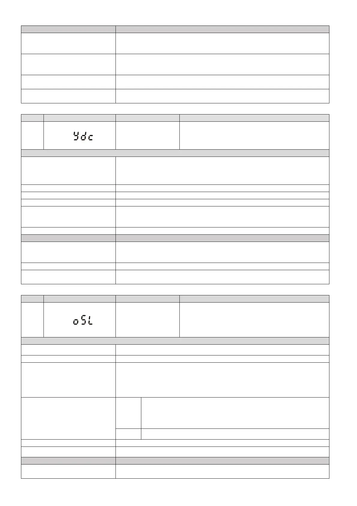
ID No. Display on LCM Keypad Fault Name Fault Descriptions
61
Y-connection /
Δ-connection
switch error
(ydc)
An error occurs when Y-Δ switches.
Action and Reset
Action level
1. ydc occurs when the confirmation signals of Y-connection and Δ-connection
are conducted at the same time.
2. If any of confirmation signals is not conducted within Pr.05-25 setting time,
ydc occurs.
Action time Pr.05-25
Fault treatment parameter N/A
Reset method Manual reset
Reset condition
Can be reset only when the confirmation signal of Y-connection is conducted if it
is Y-connection, or when the confirmation signal of Δ-connection is conducted if
it is Δ-connection.
Record Yes
Cause Corrective Actions
The electromagnetic valve
operates incorrectly during Y-Δ
switch.
Check if the electromagnetic valve works normally.
If not, replace it.
Incorrect parameter setting Check if related parameters are all set up and set correctly.
The wiring of Y-
switch function is
incorrect.
Check the wiring.
ID No. Display on LCM Keypad Fault Name Fault Descriptions
63
Over-slip
(oSL)
The slip is abnormal. By using the maximum slip
(Pr.10-29) as the base, when the drive outputs at
constant speed, and the F>H or F<H exceeds Pr.07-29
level and Pr.07-30 setting time, oSL occurs. oSL
occurs only when using a general induction motor.
Action and Reset
Action level
Pr.07-29 (100% of Pr.07-29=Pr.10-29 Top limit of frequency deviation)
Action time Pr.07-30
Fault treatment parameter
Pr.07-31
0: Warn and continue operation
1: Warn and ramp to stop
2: Warn and coast to stop
3: No warning
Reset method
Auto
When Pr.07-31=0, oSL is a “Warming”
When the drive outputs at constant speed, and the F>H or F<H no
longer exceeds the Pr.07-29 level, the oSL warning is automatically
cleared.
Manual
When Pr.07-31=1 or 2, oSL is a “Fault”. You must reset manually.
Reset condition Immediately reset
Record
When Pr.07-31=1 or 2, oSL is a “Fault”, and the fault is recorded.
Cause Corrective Actions
Check if the motor setting is
correct.
Check the motor parameter.
 Loading...
