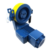
Proceed as follows to replace the brake, see also "Checking and adjusting brake air gap s
1
", Page 42:
● Unscrew the four retaining bolts of the fan cover.
● Remove the fan cover from the motor.
● Remove the retaining ring from the shaft.
● Remove the fan wheel from the shaft.
1. Remove terminal box cover (1).
Unscrew hexagon nuts (2) and remove magnet assembly (3).
2. Remove stop plate (4), armature plate (5), brake disc (6) and distance springs (7). Check collared pins (8)
and the braking surface of end cap (9) for signs of wear.
Defective parts and components and parts close to failure must be replaced.
3. If collared pins (8) or end cap (9) have to be replaced, proceed as follows:
Screw collared pins (8) out of end cap (9) and remove end cap (9) from the shaft. New collared pins (8) must
be screwed into end cap (9) with the correct tightening torque:
B004 brake = 2,3 Nm
B020 brake = 4 Nm
Push end cap (9) back onto the shaft.
4. Install brake disc (6).
Mark ("I") and bore hole (b) on stop plate (4) must be aligned with the terminal box when armature plate (5)
is fitted.
5. Push distance springs (7) onto collared pins (8).
Position brake springs (10) in magnet assembly (3); for arrangement of the brake springs, see Tab. 30,
Page 45.
Slide magnet assembly (3) over collared pins (8) and secure it with hexagon nuts (2). Tighten magnet as‐
sembly (3) with the three hexagon nuts (2) uniformly until the air gap is zero. Subsequently loosen the three
hexagon nuts (2) by angle α
1
, see Tab. 27, Page 41.
Measure air gap s
1
using a feeler gauge at three points around the circumference, see also "Checking
and adjusting brake air gap s
1
", Page 42. If the measured value is within the specified range, the motor can
be re-assembled.
Pull connecting cable (11) of magnet assembly (3) back into the terminal box, connect it and re-attach termi‐
nal box cover (1).
Arrangement of brake springs (10)
Motor Brake torque Quantity of brake springs Spring arrangement, see
Fig. 18, Page 44
[Nm] Red (RD) Blue (BU)
ZBF 63 A … B004 1,3 3 - A)
ZBF 71 A … B004 1,8 - 6 B)
ZBF 80 A … B004 3,3 3 - A)
Tab. 30
Proceed as follows for the further steps, see also "Checking and adjusting brake air gap s
1
", Page 42:
● Press the fan wheel onto the shaft and secure it with the retaining ring.
● Re-attach the fan cover to the motor with a tightening torque of 6,2 Nm.
214 395 44/120914
45
 Loading...