46
To use this pin the adjustable incisal pin
and the incisal table are removed and
the inter-bow gage pin #1 is secured in
position as shown.
Carefully and without forcing, mount the
gage components flush to the articula-
tor bows. Make sure to turn the gage
component relative to the articulator
bow in the same direction to which the
lockscrew is turned as the gage is
secured to the bow of the articulator (fig.
85).
It is important that the operator use a
consistent amount of torque when tight-
ening lockscrews to secure mounting
plates or a Field Inspection Gage to the
bows of an articulator or Lab Relator.
Tighten the lockscrew without forcing.
W
hen placing a gage component onto
the bow of an articulator the index holes
on the surface of the gage that faces the
articulator bow should be carefully and
visually located over their respective
index pin on the bow of the articulator to
prevent damage of the bearing surface
of the gage. DO NOT SLIDE THE GAGE
laterally over the index pins in an
attempt to locate the index pins in the
gage by feel. This can cause damage if
done with too much force.
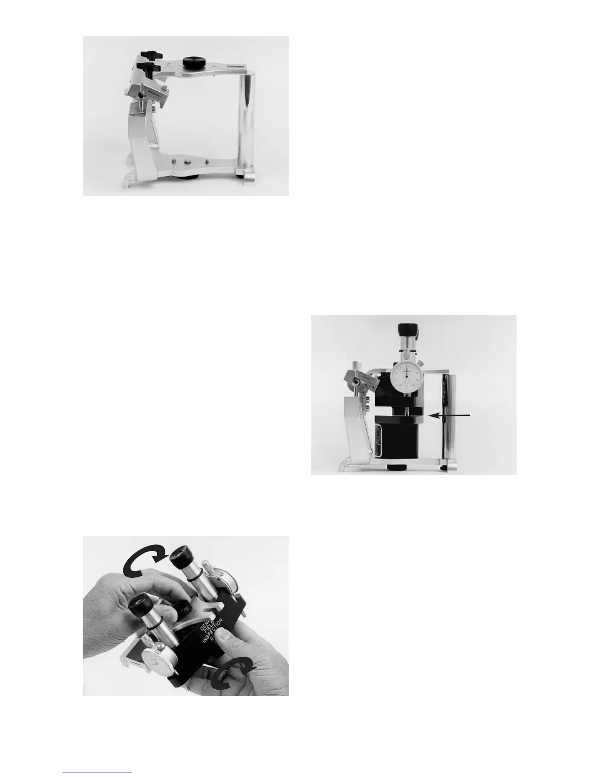
Figure 86 illustrates the Field Inspection
Gage and inter-bow gage pin 1 mount-
ed in the articulator. At this time you will
note that a space of approximately 1/4
to 1/2 millimeter exists between the
scope and the stage.
Optional: If you wish to confirm that your
gage is accurate proceed in the follow-
ing manner. On the back of the stage
you will find a calibration record as illus-
trated in fig. 87. The two large circles
represent the faces of the dial indicators
on the right and left sides of the gage as
viewed from the rear. On each circle is a
scribed calibration mark which is usual-
ly found between the +10 and +20 grad-
uations. Each graduation represents one
half-thousandth of an inch (.0005”).
These readings are the values which the
dial indicators on the respective sides of
the instruments should read when the
scope is allowed to rest on the stage
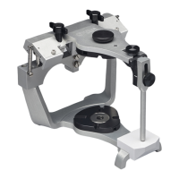
fig. 84
fig. 85
fig. 86
Space