47
by loosening the maxillary lockscrew
while the Field Inspection Gage is
mounted in an articulator or Lab Relator.
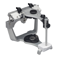
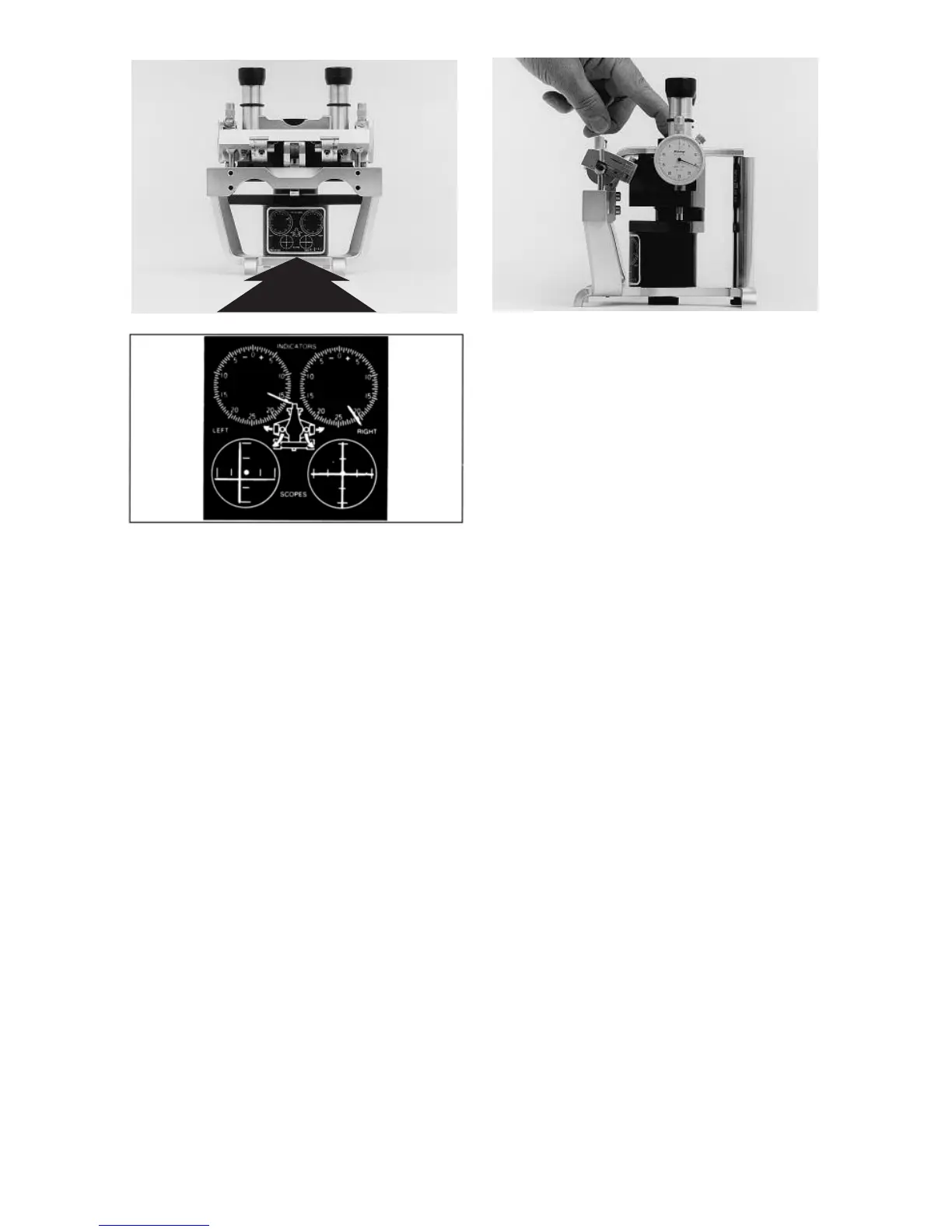
To confirm that your field gage is accu-
rate, simply loosen the maxillary
lockscrew which secures the scope to
the maxillary bow and firmly press on
the lockscrew as illustrated in fig. 88 to
insure that the scope rests on the stage.
If the dial indicators do not register the
calibration values scribed on the cali-
bration record on back of the stage,
simply loosen the lockscrew on the face
of the dial indicator (fig. 88) and rotate
the face of the indicator until the indica-
tor reads the desired value and then
lock the face in position. The field gage
is now calibrated. Resecure the scope
to the face of the maxillary bow, remem-
bering to make sure that you rotate the
face of the indicator until the indicator
reads the desired value and then lock
the face in position. The field gage is
now calibrated. Resecure the scope to
the face of the maxillary bow, remem-
bering to make sure that you rotate the
scope in the same direction that you
turn the lockscrew as you secure the
scope to the face of the articulator. At
this time the dial indicators will register
“O” if both condylar elements of the
articulator are at the correct height.
If the height of the condylar elements
are out of specification proceed in the
following manner. On the posterior
aspects of the horizontal crossbar are
vertical adjustments (A) and vertical
adjustment lockscrews (B) as illustrated
in fig. 89. Loosen the vertical adjustment
lockscrews on both sides of the articu-
lator. While applying downward pres-
sure on the maxillary bow above the
condyles, manipulate both vertical
adjustments until both dial indicators
read +5 to +10. A plus reading indicates
that the condyles are below the desired
height. Note that when you change the
height of one condyle it affects the read-
ing on both dial indicators. Snug the
vertical adjustment lockscrews to firmly
seat the pins supporting the condylar
elements in their housings but do not
tighten all the way. At this time both
condylar elements are just below the
desired height. Alternately tighten the
vertical adjustment screws in small
increments on the right and left sides of
the instrument until both dial indicators
read “O”. Tighten the vertical
fig. 87
fig. 88