48
adjustment lockscrews to secure the
condylar elements in this position.
HORIZONTAL ALIGNMENT
The articulator must be in specification
in the vertical dimension before horizon-
tal alignment is made.
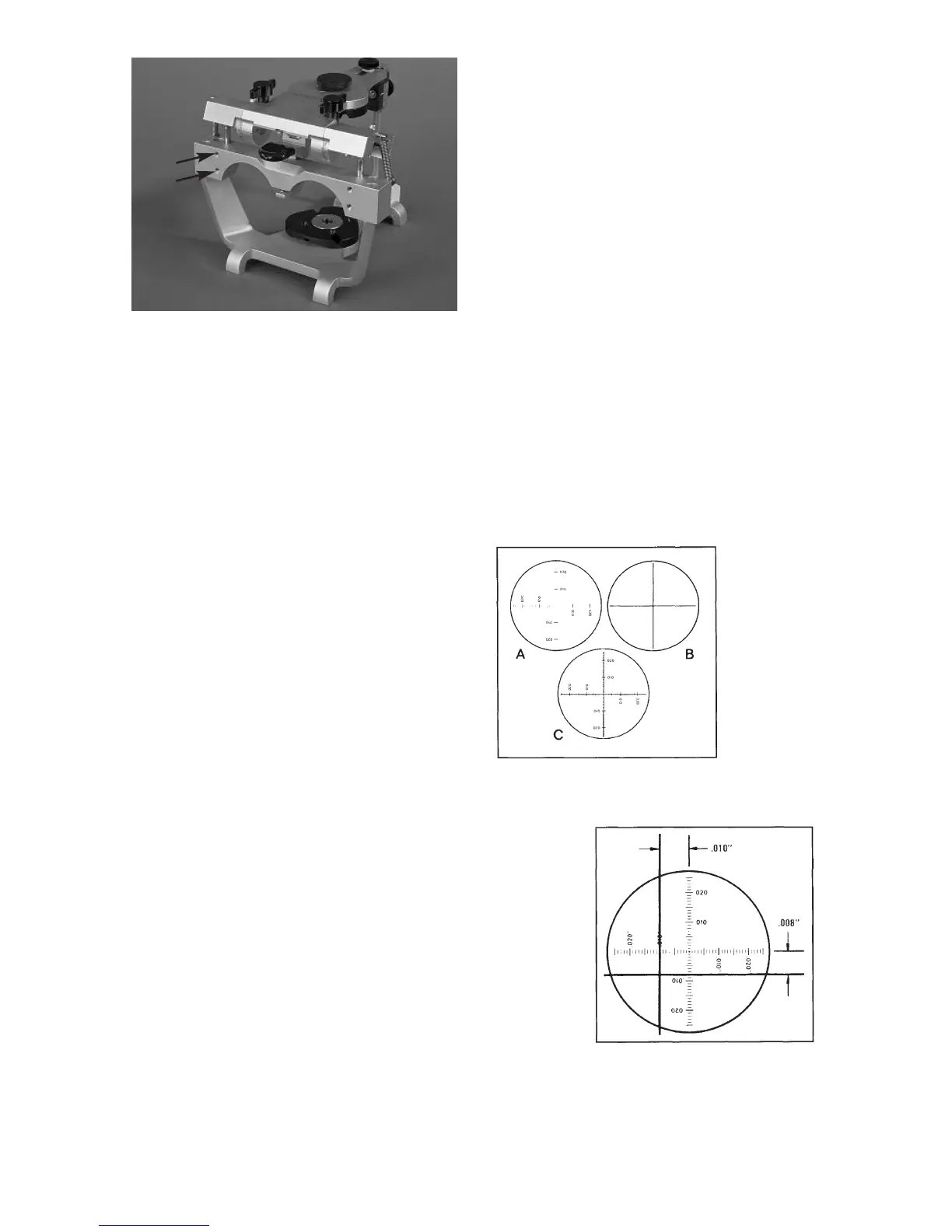
On the scope member of the Field
Inspection Gage are two forty power
(40x) monocular scopes. You are to look
through these scopes one at a time. In
each scope is a reticle graduate in one
thousandths of an inch (.001”) incre-
ments in four directions off of a centric
dot as illustrated in figure 90A. On the
lateral wings of the stage are crosshair
targets as illustrated in figure 90B. If an
articulator is in perfect specification
anterior-posteriorly and medio-laterally,
the intersection of the target crosshairs
will touch the centric dot of the reticle as
in figure 90C when viewed through the
scope. If the articulator is out of specifi-
cation as illustrated in figure 91, the
amount it is out of specification can be
measured with the graduated reticle. For
example, figure 91 illustrates the view
through the scope of an articulator out
of specification ten thousandths of an
inch (.010”) medio-laterally and eight
thousandths of an inch (.008”) anterio-
posteriorly.
To align an articulator in the horizontal
plane, proceed in the following manner.
O
n the back of the stage is a calibration
record as illustrated in figure 87. The
two small circles on the lower portion of
the record are the calibration records for
the scope’s on the respective sides of
the articulator. Each graduation off of
the centric dot represents one thou-
sandths of an inch (.001”). the total
diameter of each small circle represents
a little over four thousandths of an inch
(.004”), or about the thickness of normal
writing paper. In each of the small circles
you find a scribed cross mark. This mark
represents the true centric position. In
other words, when you look through the
monocular scopes, the true centric
position in some gages is that position
indicated by the scribed cross marked
on the calibration record.
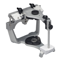
fig. 89
fig. 90
fig. 91
A
B