49
T
his calibration system is used because
in manufacture, slight creepage of the
centric dot of the reticle can occur. This
calibration system allows for corrections
of this error and maximum accuracy.
In the following instructions to adjust the
horizontal alignment of the articulator, it
is assumed that the scribed crosses
marked on the calibration record coin-
cides with the centric dots of the reticle.
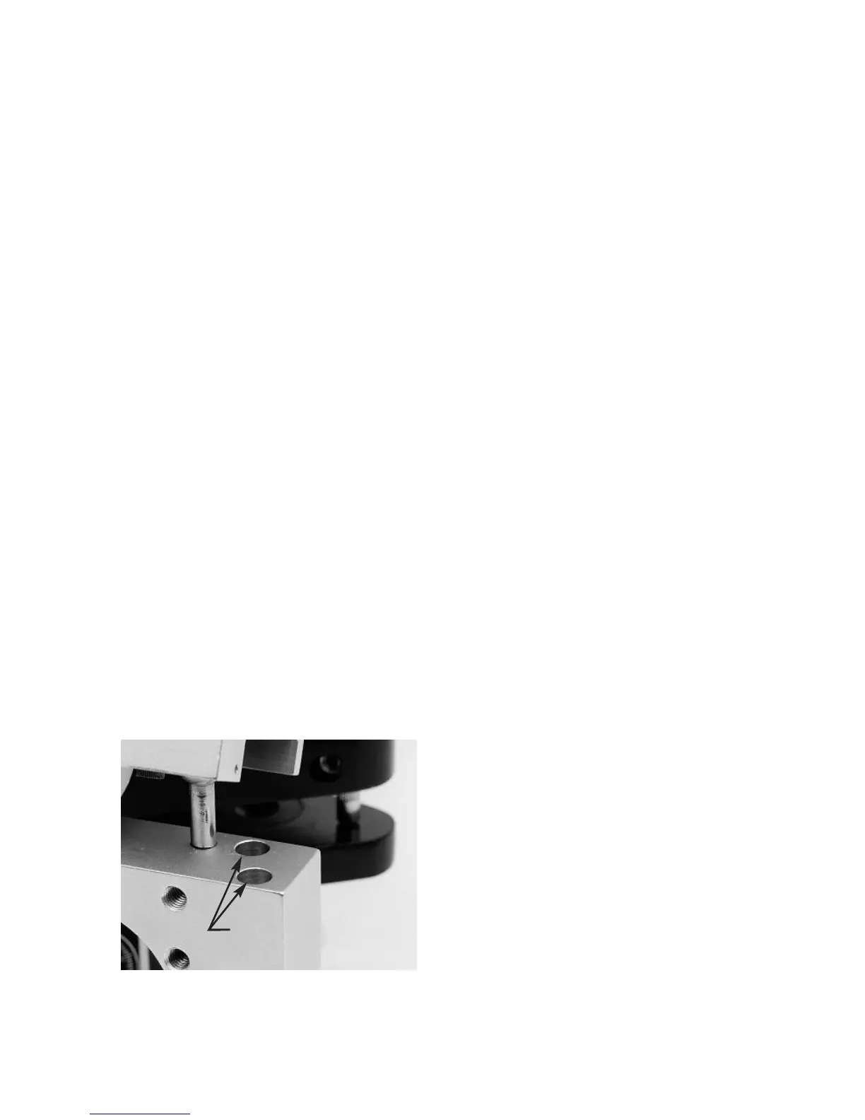
Loosen the horizontal adjustment
lockscrews illustrated in figure 92 on
both sides of the articulator the mini-
mum amount necessary to allow hori-
zontal crossbar. Engage the centric
latch of the articulator. While maintain-
ing slight downward pressure on the
horizontal crossbar of the lower member
of the articulator to keep the horizontal
crossbar seated flush on the crossbar
supports, slide the horizontal crossbar
and maxillary bow assembly in the hori-
zontal plane until the centric dots are on
the junction of the crossbar targets as
viewed through both scopes. Then while
carefully maintaining this crossbar posi-
tion incrementally tighten in a crisscross
sequence the four horizontal adjustment
lockscrews.
The articulator in now calibrated in the
centric position.
RUN-OUT INSPECTION
PROCEDURE
The articulator was aligned by means of
the Field Inspection Gage with the pro-
trusive condylar path inclinations set to
30 degrees. Readjust the right protru-
sive condylar path to 10 degrees and
tighten the lockscrew. Record the read-
ing on the right dial indicator. The two
readings indicate the amount of run-out
of the articulator adjustment. Factory
specifications require that all articulators
have a run-out of less than plus or
minus five thousandths of an inch
(+.005”).
REINSERTION OF THE
ADJUSTABLE INCISAL PIN
After an articulator is properly aligned by
means of a Field Inspection Gage, the
most convenient way to set the
adjustable incisal pin to an accurate
zero position is to remove the incisal pin
#1 and reinsert the incisal table and
adjustable incisal pin set to zero. If the
dial indicators do not read zero the
height of the adjustable incisal pin can
be minutely adjusted until the dial indi-
cators read zero.
INTER-BOW GAGE PIN #2
Inter-bow gage pin #2 is used to pre-
cisely adjust incisal pins to the zero
dimension in articulators and Lab
Relators known to be in specification.
The incisal pin is raised and the inter-
bow distance is established by means
of the inter-bow gage pin #2, as illustrat-
ed in figure 93.
The adjustable incisal pin is then adjust-
ed and secured to maintain the inter-
bow distance established by the inter-
bow gage pin #2. It is important to apply
downward pressure on the top of the
adjustable incisal pin as the lockscrew is
tightened to prevent upward creepage
of the incisal pin when tightening the
lockscrews as illustrated in figure 94.
fig. 92
Horizontal
Adjustment Screws