10
FT Range SP20001_REV_2
The FT cylinder is fi xed in
position in self-aligning
bearings with aluminium
housings spigotted to the
side frames. The bottom
blade assembly is
adjusted up and down by
using a knurled knob
system.
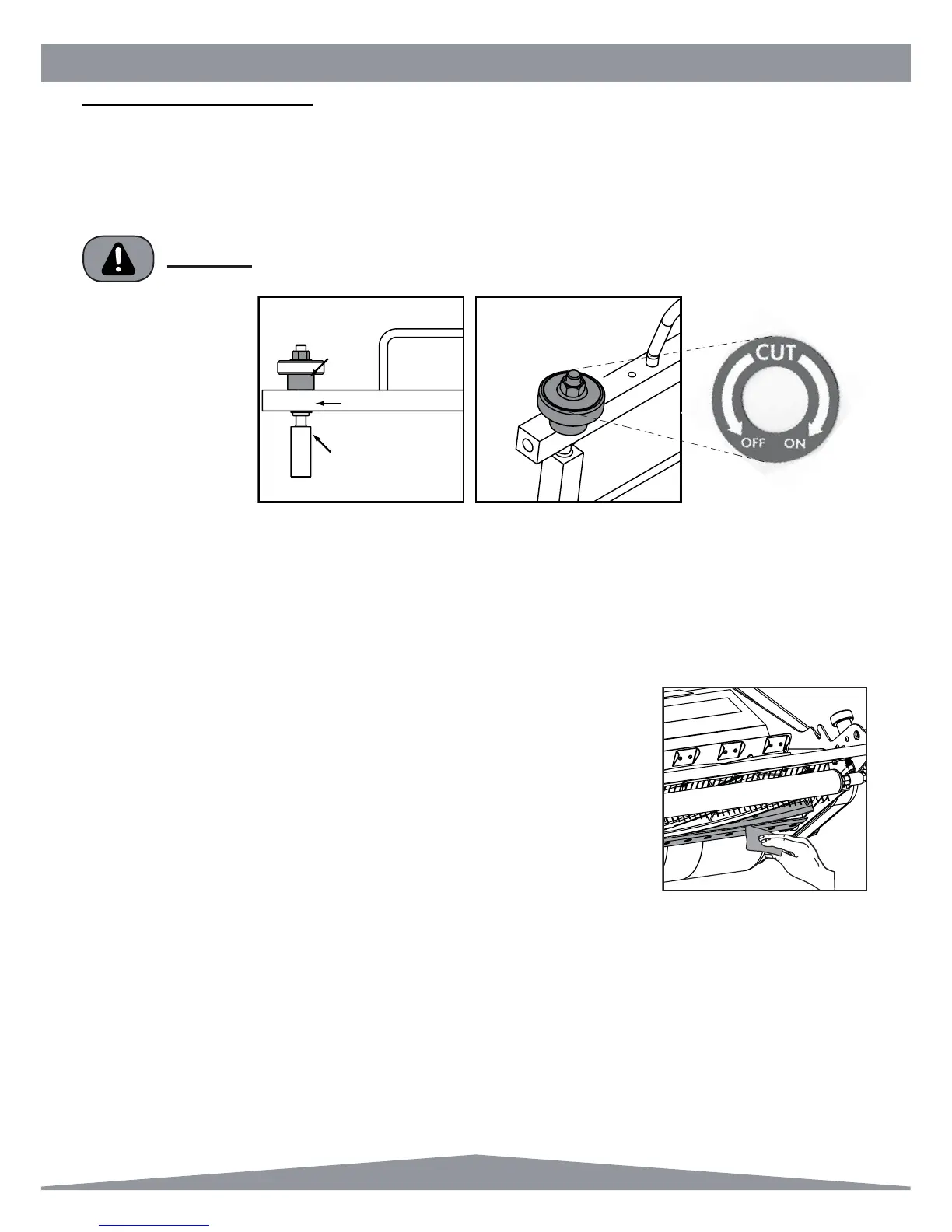
To operate this system
fi rstly slacken the two locknuts
on the adjuster stems – The Lock Nut (A) is directly on top of the Knurled Knobs (B). Use a 9/16 AF spanner. Each
knurled knob has a decal to indicate ON or OFF cut. ON cut brings the bottom blade closer to the cylinder. OFF cut
moves it away.
A = Locknut (9/16” Spanner)
B = Lubricate occasionally with Oil
C = Circlip
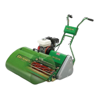
Rotate the knurled knobs to gain light contact between the shear blade and cylinder on
both sides of the cassette. The adjustment should be made so that the cylinder will spin
with a light audible contact with the bottom blade. Check the setting using thin paper
along the length of the cylinder adjusting until it cuts along its whole length.
When a satisfactory set is achieved tighten the lock nuts whilst holding the knurled knob
fi rmly (to stop it turning), recheck adjustment.
Do not set the cylinder hard on, as this will cause excessive wear of the cylinder, bottom
blade the drive system and increase fuel consumption.
General Adjustments
CUTTER SETTING ADJUSTMENT
For cutter cylinder cassettes (5 or 9 blade units).
For a full view of the setting operation we suggest you remove the cassette from the machine and place on the back fl at
edge of the frame at a comfortable height. It is now possible to make adjustments in the machine without cassette
removal should you prefer.
CYLINDERS AND BOTTOM BLADES ARE SHARP, WEAR GLOVES TO PROTECT YOUR
HANDS AND FINGERS.
WARNING