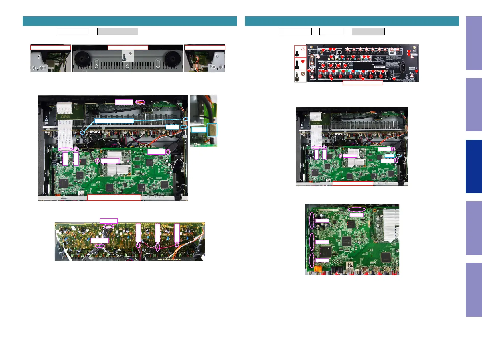
Proceeding : TOP COVER → RADIATOR ASSY
(1) Removethescrews.
(2) Cutthewireclamps,thenremovetheCORDHOLDERsandconnectors.
RemovetheTAPE.RemovetheFFC.
(3) Removetheconnector.
2. RADIATOR ASSY
View from the bottom
↓Shooting direction: C↓ ↑Shooting direction: D↑
x7
↑Shooting direction: A↑
CP4400
FFC
FFC
N1008
N1000
CORD HOLDER
CUT
TAPE
CP401
CP402
CP403
CP405
CP404
Proceeding : TOP COVER → WiFi ANT → DIGITAL PCB
(1) Removethescrews.
(2) Removethescrews.Cutthewireclamp,thenremovetheCORDHOLDERandconnector.
RemovetheFFC.
(3) Removetheconnector.
3. DIGITAL PCB
↑Shooting direction: A↑
x26
x14
x2
x2 E3 ONLY
↑Shooting direction: A↑
FFC
FFC
N1008
N1000
N1033
CUT
N1039
N1014
N1016
N1020
Before Servicing
This Unit
Electrical Mechanical Repair Information Updating
70
 Loading...