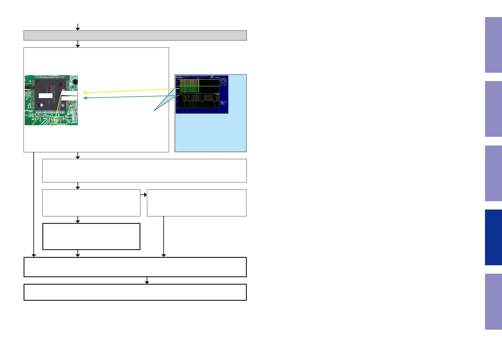
Check item(3-4.4.). Check the I2C communication line :
Check the CPU.
Is the "I2C" waveform of the TP near the CPU [U1018] correct (like
the one shown in the diagram) when the power is turned on?
U1018
AVSDA
AVSCL
Check item(3-4.5.). Check the I2C communication line :
Check GUI [U1026], HDMI SW[U1103] and CPU[U1018] patterns as well as soldering.
If there is no problem, go to the next step.
Check the CPU.
Remove the damping resistor [R1493/R1494]
of [U1018].
Is the "I2C" waveform correct?
The CPU [U1018] is faulty.
Replace with a new device.
Check the I2C communication line.
GUI [U1026] is faulty.
Replace with a new device.
GUI [U1026] is faulty.
Replace with a new device.
YES
*The diagram shows an example.
(Signal patterns vary depending on the tim-
ing.)
Points for checking waveforms
- Crest value (3.3V normally)
- Signal change
- SCL frequency (400kHz normally)
Voltage scale:1.0V/div
Time scale:10us/div
NO
YES
YES
NO
Recheck from check item (3.1.).
If it does not work, replace the PCB.
Before Servicing
This Unit
Electrical Mechanical Repair Information Updating
99
 Loading...