


J
Janice AtkinsonAug 12, 2025
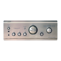
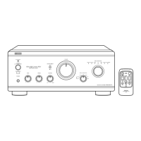
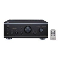
Why won't my Denon PMA-2000IVR turn on?
- AarthurthomasAug 12, 2025
If the MUTE/STANDBY LED on your Denon Amplifier doesn't light up and no sound is produced when you turn the power switch on, make sure the power supply cord is properly connected.