EasyManua.ls Logo

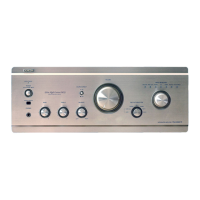
Denon PMA-2020AE Service Manual

Denon PMA-2020AE
50 pages
To Next Page IconTo Next Page
Page #1 background imageLoading...
Page #1 background image
D&M Holdings Inc.
SERVICE MANUAL
e
e
Copyright 2012 D&M Holdings Inc. All rights reserved.
WARNING: Violators will be prosecuted to the maximum extent possible.
MODEL JP E3 E2 EK EA E1C E1K EUT
PMA-2020AE
P P
INTEGRATED AMPLIFIER
Ver. 2
S0569-1V02DM/DG1210
Some illustrations using in this service manual are slightly different from the actual set.
Please use this service manual with referring to the operating instructions without fail.
• For purposes of improvement, specications and design are subject to change without notice.
Please refer to the
MODIFICATION NOTICE.

Other manuals for Denon PMA-2020AE

Questions and Answers:

Denon PMA-2020AE Specifications

General IconGeneral
Amplifier class-
Input sensitivity135 mV
Audio output channels2.0 channels
Peak power per channel160 W
Signal-to-Noise Ratio (SNR)108 dB
Total Harmonic Distortion (THD)0.01 %
AC (power) inYes
Audio (L/R) in7
Audio (L/R) out2
Headphone outputs1
PurposePerformance/stage
Product colorSilver
Connectivity technologyWired
AC input voltage100-240 V
AC input frequency50 - 60 Hz
Power consumption (standby)0.2 W
Power consumption (typical)310 W
Weight and Dimensions IconWeight and Dimensions
Depth435 mm
Width434 mm
Height181 mm
Weight24400 g

Summary

General Safety Precautions

Leakage Current Check Procedure

Outlines the procedure for checking leakage current before returning the unit.

Servicing and Inspection Cautions

Highlights important cautions to follow during servicing and inspection procedures.

Important Safety Parts Identification

Explains how safety-critical parts are indicated and the importance of using designated replacements.

Technical Specifications Overview

Power Amplifier Section Specifications

Details the performance metrics for the unit's power amplifier stage.

Pre-Amplifier Section Specifications

Lists the input sensitivity, impedance, and RIAA deviation for the pre-amplifier.

Overall Performance and General Specs

Covers S/N ratio, tone control, power supply, and consumption details.

Unit Disassembly Procedures

Idling Adjustment

Idling Adjustment Setup

Describes the preliminary setup steps required before performing idling adjustment.

Troubleshooting Guide

Power On Failure (No LED)

Provides troubleshooting steps for when the unit does not power on.

No Sound Output (Dual Channel)

Guides diagnosis for cases with no sound output in both channels.

No Sound Output (Single Channel)

Offers troubleshooting steps for when sound output is missing in only one channel.

Block and Level Diagram Analysis

Wiring Diagram Reference

Printed Wiring Board Layouts

Schematic Diagrams Part 1

Schematic Diagrams Part 2

Schematic Diagrams Part 3

Schematic Diagrams Part 4

Schematic Diagrams Part 5

Exploded View Assembly

Exploded View Parts List

Semiconductor Components

IC Diagrams and Application Circuits

PCB Unit Parts Lists

Power Amp PWB Unit Parts List

Flat Amp PWB Unit Parts List

Related product manuals