7
OUTPUT Power DC12 V
1-2 Output DC12v (max 200mA) for electrical connection of local devices connected to the board.
It can be used to power a local PIR or a remote receiver. It is recommended not to overload the output.
OUTPUTS
3 ARD/SHP - Reports the ARMING status (W2 open), or is active when TRIG is in progress (W2 close).
4 EMPTY - reports the fluid EMPTY condition.
5 ERROR - reports a transient error or fault condition that voids functionality.
It also activated when maintenance is needed, eg. faulty battery , mains power fault or detected temperature out of
range.
If a mains power fault occurs it will be self resetted when correct mains power is back. We remind that it is necessary
to connect this output to an alarm control panel or other equipment able to forward the signal to whom is concer-
ned.
INPUTS
6 GND Reference GND for the inputs.
7 ARM Closing the contact ARM: the blue led turns ON and then, if the unit has reached the correct temperature,
is ready to generate fog. During the shot, if the contact ARM is opened, it immediatly stops fog generation.
8 TRIG Closing the contact TRIG, if the unit is armed and has reached the correct temperature, it generates fog for
the time set.
After the shot, all further shot commands within 120 seconds will not be processed.
In order to avoid accidental activations with consequent fog emission, the inputs are in "negative safety",
so the disconnection of a wire does not cause the activation.
It is essential to carefully check the reliability of the connections and protect the cables to the alarm control unit
where there is a risk of accidental or malicious void.
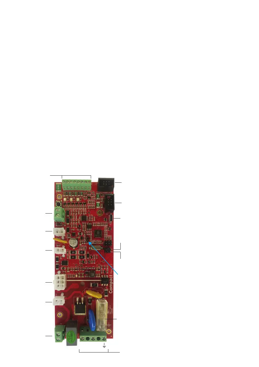
A) J4 Mains power connection
B) J5 Heater Resistor
C) J2 Thermal CutO
D) J7 Power supply unit 230v AC/12v DC
E) J9 Battery 12v 1.2A connector
F) J8 Thermal Sensor connector
G) J10 Inputs/Outputs connector
H) J11 RS232 port 1 connector
I) J6 RS232 port 2 connector
J) J3 Fluid Pump Connector
L) J1 USB port
M) F4 Mains fuse
W1 Shooting time setting enable
W2 Default open (see paragraph 10)
W3 Reserved (Open)
G
H
F
J
D
C
B
W1
I
W3
W2
L
M
N L
A
E