8
10. Connection examples
The diagrams and examples below are intended only for a “better understanding” of the operation of the
inputs/outputs. None of the diagrams below represents the “single scheme to perform” as, in respect of the reference
standard EN50131-8:2019, there are precise indications and only using all inputs and outputs on the PCB it is possible
to abide by the standard.
Is recommended to use the “HOLD-UP” function after a careful evaluation of the risks from a security consultant.
When Density
®
Basic is ARMED, it becomes immediately ready to create fog.
For safety reasons and to avoid false fog emissions is suggested to program the alarm panel to allow enough time to
leave the place.
The ON/OFF output of this alarm panel is an Open Collector NPN that is OPEN with the
alarm OFF and close to negative for all the time the alarm panel is active and monitoring.
The alarm panel output is normally open and close the contact during alarm time.
A Density
®
Basic inputs connected to standard alarm panel outputs
B Density
®
Basic inputs connected with a clean contact (relays) alarm panel outputs
C Wiring example of Density
®
Basic outputs to drive leds and/or relays
Note: in the following examples the output signal ARD/SHP has the following meaning
depending on jumper W2:
W2 OPENED=ARM STATUS reported
W2 CLOSED=SHOT in PROGRESS STATUS reported
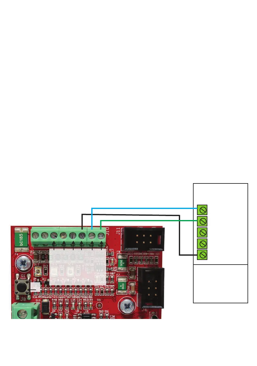
A - Density® Basic inputs connected to standard alarm panel outputs
Alarm system panel
NPN output
Open Collector
OC1 NO BISTABLE
OC2 NO
MONOSTABLE
OC
OC
GND
S1
81
TRIG
ARM
ARD/SHP
EMPTY
FAULT
GND
OC: Open Collector
NO: Normally Open
GND: Ground
NC: Normally Closed