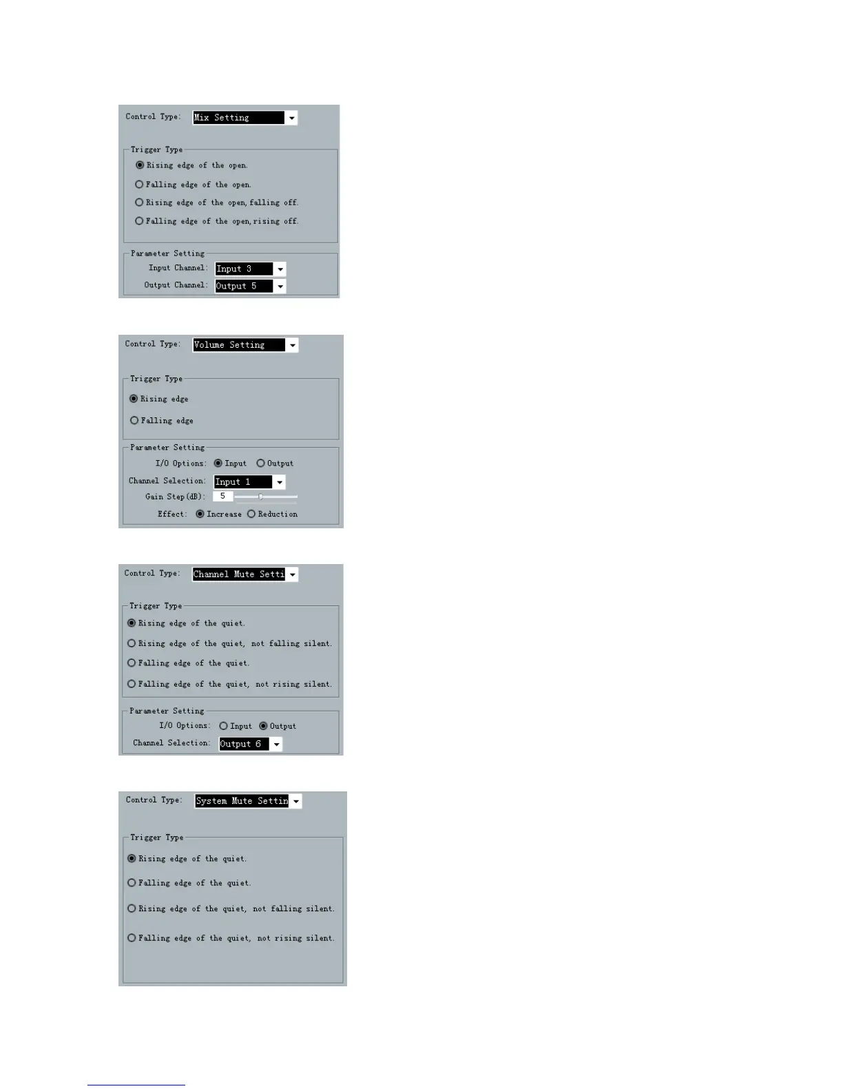
When the GPIO Channel is input 2, the mixer
setting should be selected as the Control Type. As is
shown in the chart, when the level of GPIO input
channel 2 is changed from low to high, the sound
mixing contacts corresponding to input channel 3 and
output channel 2 will be opened, and the signals of
input channel 3 will be mixed and transmitted to output
channel 2 and then the signals will be output. If the
trigger type is trigger mode 4 (Falling edge of the open,
rising off),
the contacts corresponding to the input
channel 3 and output channel 2 of the key sound mixer
will be closed when electrical level of the pin of GPIO
input channel 2 is changed from low to high.
Input/output type refers to the input sound
volume/output sound volume of the control system.
Gain Step refers to the dB change corresponding to
the step of the adjusted sound volume due to each
trigger; and there are two effects, i.e. Increase
and Decrease, which refers to the increased or
decreased sound volume caused by each trigger.
As is shown in the chart, the level of input
channel 1 will be increased by 5 dB when electrical
level of GPIO input channel2 is changed from low to
high.
d
As is shown in the chart, output channel 3 is be
muted when the level of the pin of GPIO input
channel 2 is changed from low to high.
As is shown in the chart, all the system output
channels are muted when the level of GPIO input
channel 5 is changed from low to high.
f