7. 1 95-86668
JUNCTION BOX COVERS
To ease installation and future removal, ensure that the
threaded junction box covers are properly lubricated.
If additional lubrication is required, use Lubriplate
grease (see the “Ordering Information” section for part
number).
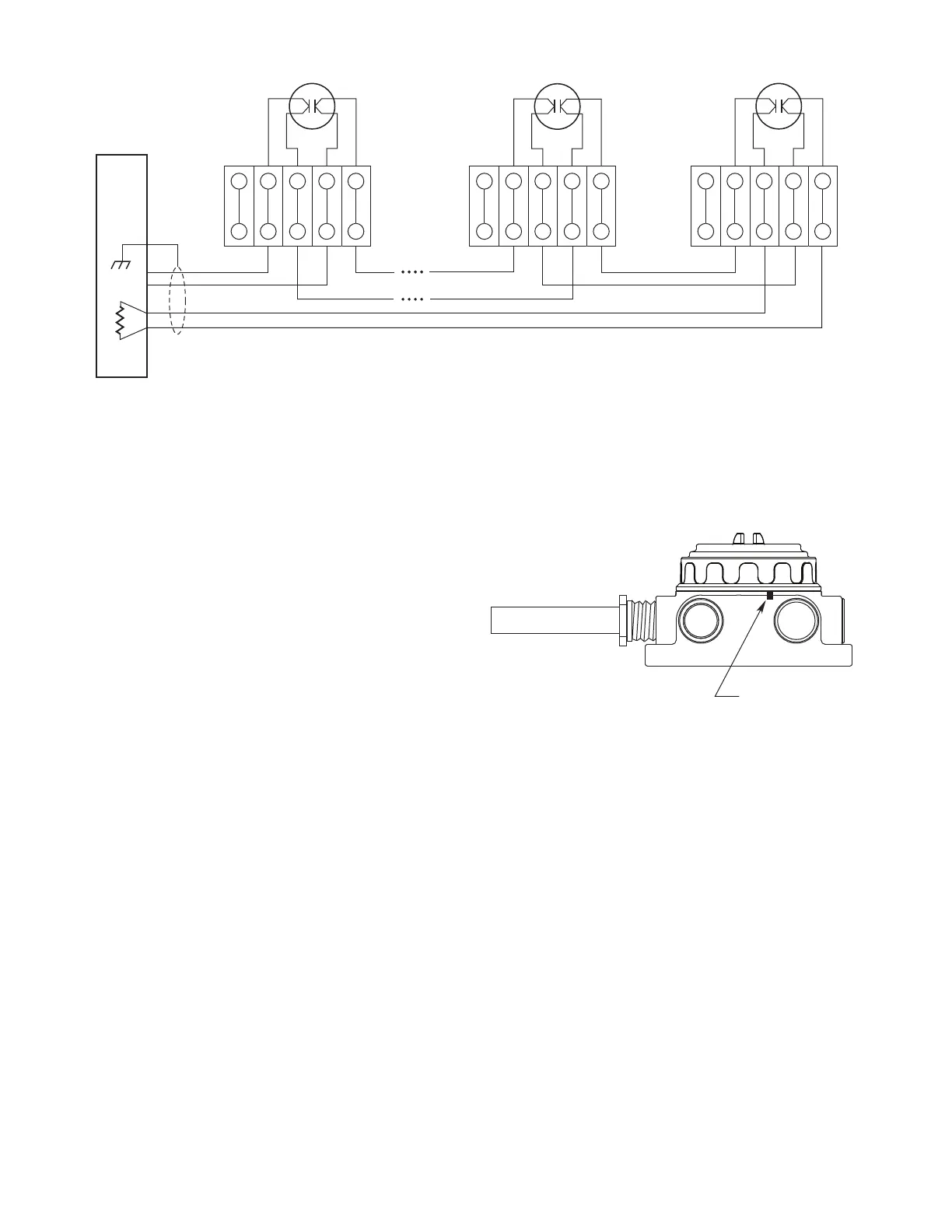
When tightening the junction box cover, ensure that the
O-ring is properly engaged.
The hex head set screw on the base of the junction box,
located near port 2, should be tightened to secure the
cover and prevent access to the wiring compartment
without the use of a tool. See Figure 13 for location.
FIRE
ALARM
PANEL
1
6
2
7
3
8
4
9
5
10
EOL
RESISTOR
1
6
2
7
3
8
4
9
5
10
1
6
2
7
3
8
4
9
5
10
B2564
HEAT
DETECTOR
B B W W
HEAT
DETECTOR
B B W W
HEAT
DETECTOR
B B W W
Figure 12—Typical Ex d e Wiring - 4 Wire with Open Circuit Monitoring
Figure 13—Location of Cover Locking Set Screw
HEX HEAD SET SCREW
A2597