7. 1 95-86664
WIRING PROCEDURE
Wire Size and Type
The system should be wired according to local codes.
The wire size selected should be based on the number
of detectors connected, the supply voltage and the
cable length. Typically 16 AWG, 2.5 mm
2
shielded
cable is recommended. Wires should be stripped 3/8
inch, 9 mm.
The use of shielded cable is required to protect against
interference caused by EMI and RFI. When using
cables with shields, terminate the shields as shown in
Figures 4 through 7, and Figures 9 through 12. Consult
the factory if not using shielded cable.
In applications where the wiring cable is installed in
conduit, the conduit must not be used for wiring to
other electrical equipment.
If disconnection of power is required, separate
disconnect capability must be provided.
WARNING
All entries must contain appropriately rated
plugs or ttings. It is required that each plug or
tting be wrench-tightened to an appropriate
installation torque and meet the minimum thread
engagement requirements per the applicable
local standards, codes, and practices in order
to retain the dened ratings. PTFE sealant or
equivalent should be used on NPT threads.
IM PORTANT
Devices certied for hazardous locations shall
be installed in accordance with EN/IEC 60079-14
and NEC 505.
CAUTION
Installation of the detector and wiring should be
performed only by qualied personnel.
Wiring Temperature Requirement
For ambient temperature above 60°C use field wiring
suitable for maximum ambient temperature. For
temperature below –10°C use field wiring suitable for
the lowest temperature.
End-of-Line (EOL) and Short-Circuit-Monitoring
(SCM) Resistors
To ensure that the insulating material of the wiring
terminal block will not be affected by the heat generated
by EOL and SCM resistors, observe the following
guidelines when installing the resistors.
1. Required EOL and SCM resistor power rating
must be 5 watts minimum and must be ceramic or
wirewound type, with actual power dissipation not to
exceed 2.5 watts.
NOTE
Refer to the Ordering Information section of this
manual for information regarding EOL and SCM
resistors. Use Det-Tronics parts or equivalent.
2. Resistor leads should be cut to a length of
approximately 1 1/2 inches, 40 mm.
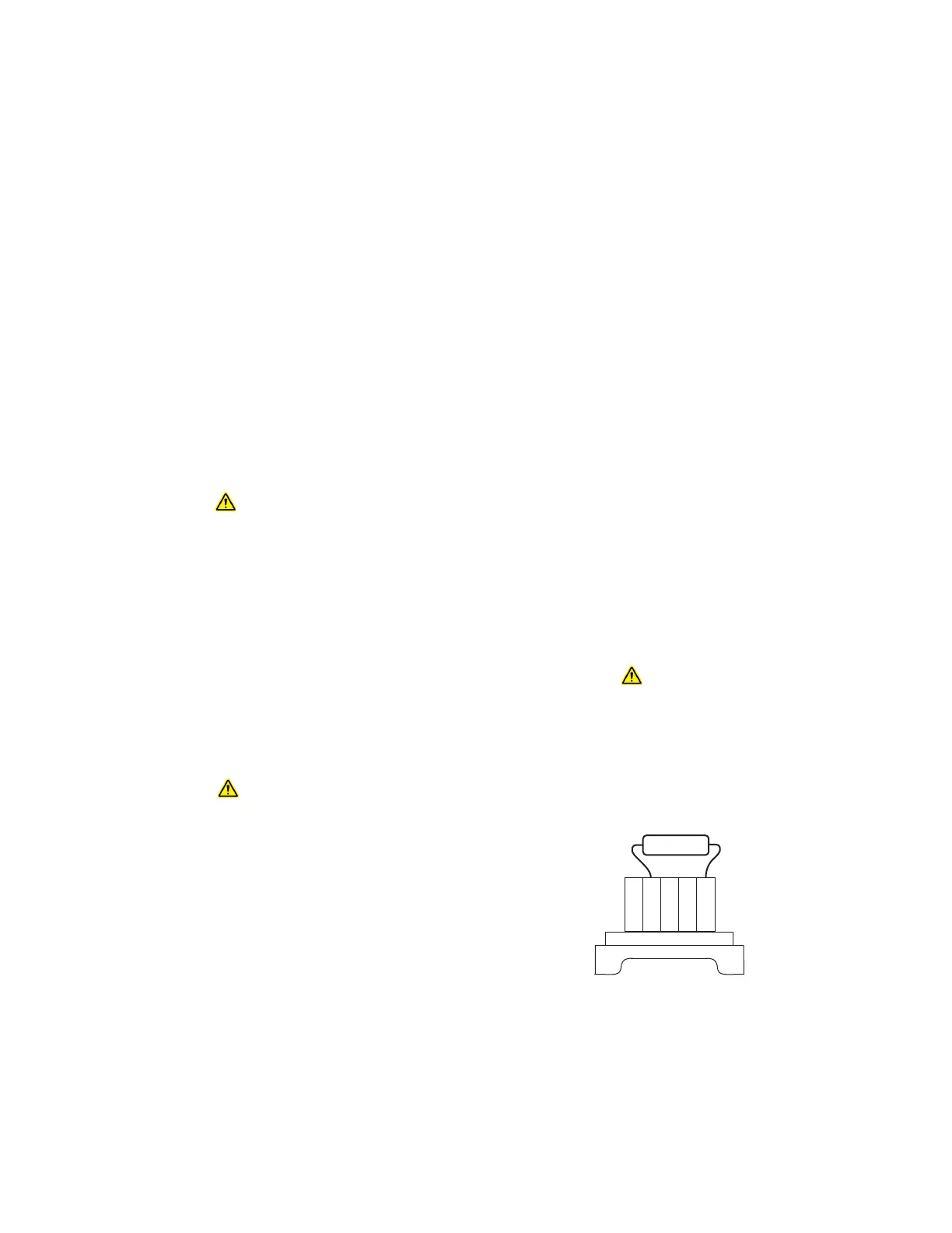
3. Bend the leads and install the EOL or SCM resistor
as shown in Figure 1.
4. For Ex e installations, the EOL resistor must be
located at the fire panel (refer to Figure 7). The SCM
resistor is not to be used in Ex e installations.
NOTE
All cable entry devices and blanking elements
shall be certied, suitable for the conditions of
use, and correctly installed. Unused junction box
entries must be closed with suitable and correctly
installed plugs.
WARNING
Always ensure that the detector hazardous
(classied) location ratings are applicable for the
intended use.
A2559
Figure 1—Resistor Installation