7. 1 95-86665
Detector Wiring
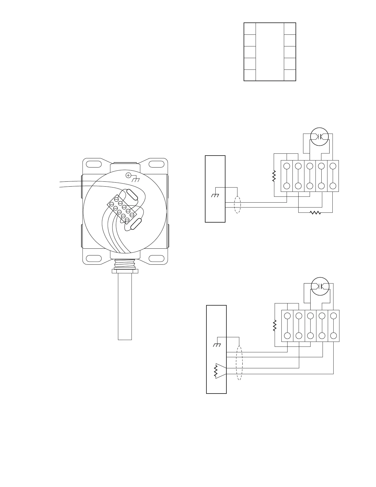
Figure 2 shows the wiring terminal strips within the
junction box.
Figure 3 shows the recommended wiring connections
for a single detector.
Figures 4 thru 7 show single detectors wired in a variety
of typical configurations.
Figure 8 shows the wiring connections for daisy chained
detectors.
Figures 9 thru 12 show daisy chained detectors wired in
a variety of typical configurations.
3
4
5
2
1
6
7
8
9
10
2560
Figure 2—Wiring Terminal Identication
B2581
1
5
10
6
W
B B
W
EOL
SCM
TO
FIRE
ALARM
PANEL
Figure 3—Recommended Ex d Wiring Connections -
2 Wire with Open and Short Circuit Monitoring
EOL
RESISTOR
1
6
2
7
3
8
4
9
5
10
SCM
RESISTOR
HEAT
DETECTOR
B B W W
FIRE
ALARM
PANEL
B2582
Figure 4—Typical Ex d Wiring - 2 Wire with Open and
Short Circuit Monitoring
FIRE
ALARM
PANEL
EOL
RESISTOR
1
6
2
7
3
8
4
9
5
10
SCM
RESISTOR
B2583
HEAT
DETECTOR
B B W W
Figure 5— Typical Ex d Wiring - 4 Wire with Open and
Short Circuit Monitoring