H-3 95-852613.1
SETTING NETWORK ADDRESSES
Overview of Network Addresses
Each PIRECL IR gas detector on the EQP LON must be assigned a unique address. Addresses 1 to 4 are reserved for
the EQP controller. Valid addresses for field devices including PIRECL gas detectors are from 5 to 250.
IMPORTANT
If the address is set to zero or an address above 250, the system will ignore the switch setting and the device.
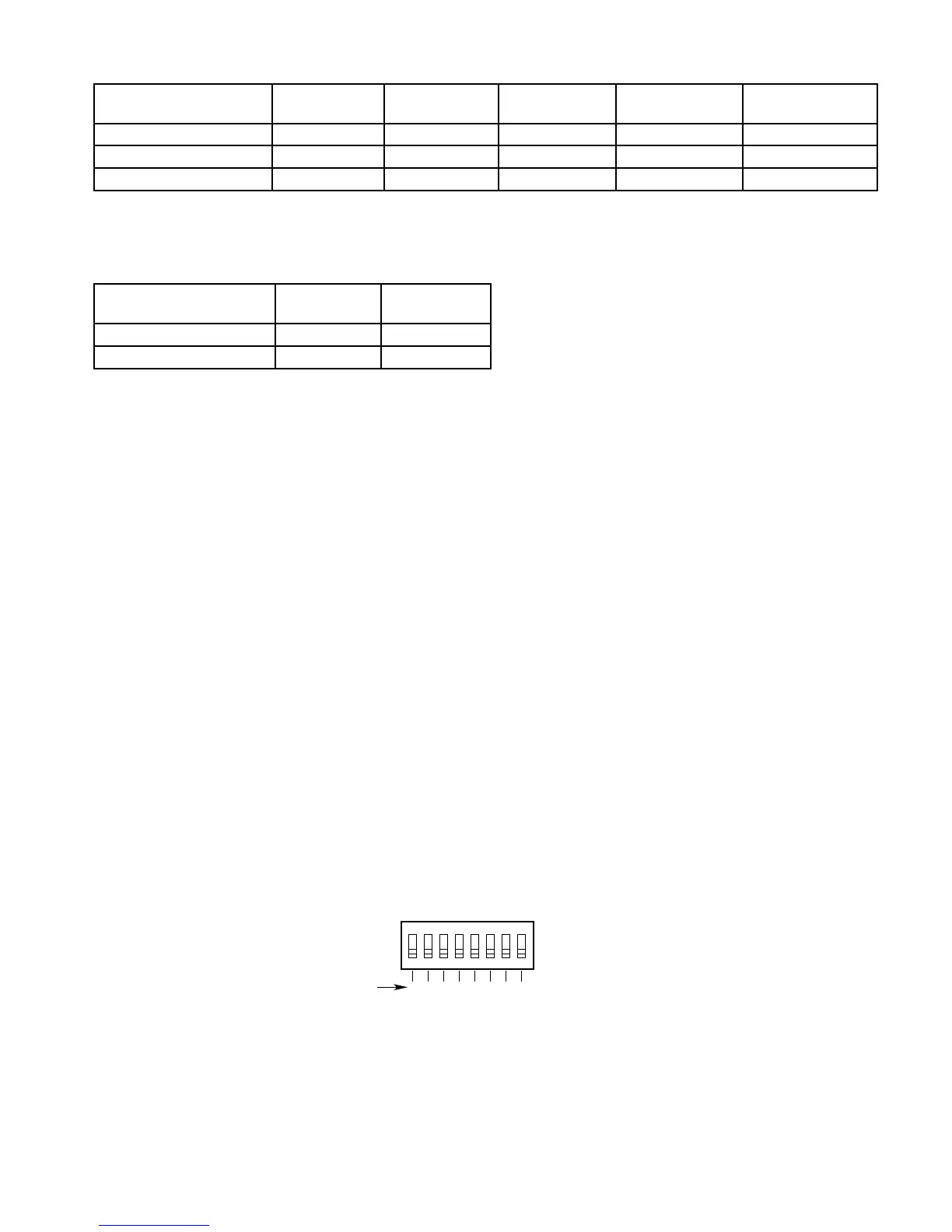
TheLONaddressisprogrammedbysettingrockerswitchesonan8switch“DIPSwitch”locatedwithinthePIRECL
housing. The address number is binary encoded with each switch having a specific binary value with switch 1 being
the LSB (Least Significant Bit). (See Figure C-1.) The device’s LON address is equal to the added value of all closed
rockerswitches.All“Open”switchesareignored.
Example:fornodeNo.5,closerockerswitches1and3(binaryvalues1+4);fornodeNo.25,closerockerswitches
1, 4 and 5 (binary values 1 + 8 + 16).
NOTE
For convenience in setting LON address switches, a “Rocker Switch Table” is included in the EQP System
manual (form 95-8533).
Table H-4—PIRECL Faults and Fixed Logic System Outputs
1 2 3 4 5 6 7 8
1 2 4 8 16 32 64 128
ON
NODE ADDRESS EQUALS THE ADDED VALUE
OF ALL CLOSED ROCKER SWITCHES
A2190
BINARY
VALUE
CLOSED = ON
OPEN = OFF
Figure H-1—PIRECL Address Switches
Table H-3—PIRECL Fixed Alarm Logic (Thresholds Programmed Using S3 Conguration Software)
Field Device Fire
Alarm
High Gas
Alarm
Low Gas
Alarm
Trouble Supervisory
PIRECL (Point IR Eclipse)
High Alarm X
Low Alarm X
Field Device VFD Faults Trouble
LED
Trouble
Relay
Calibration Fault X X
Dirty Optics X X