MOTHERBOARD REPLACEMENT PROCEDURE
To replace a defective motherboard:
CAUTION
Do not open the detector housing in a hazardous
location without first removing power, including
power to the relay contacts.
1. Remove power from the detector and relay con-
tacts.
2. Loosen the six screws and remove the junction
box cover (see Figure 15).
3. Disconnect all field wiring from the detector termi-
nal blocks. Note all wire locations to assure prop-
er reconnection. See Figure 4.
4. Remove the three screws that secure the mother-
board assembly to the inside of the junction box.
Remove the motherboard.
5. Note the position of the jumper plugs on the moth-
erboard that is being replaced, then install the
jumpers on the new motherboard in the same
positions.
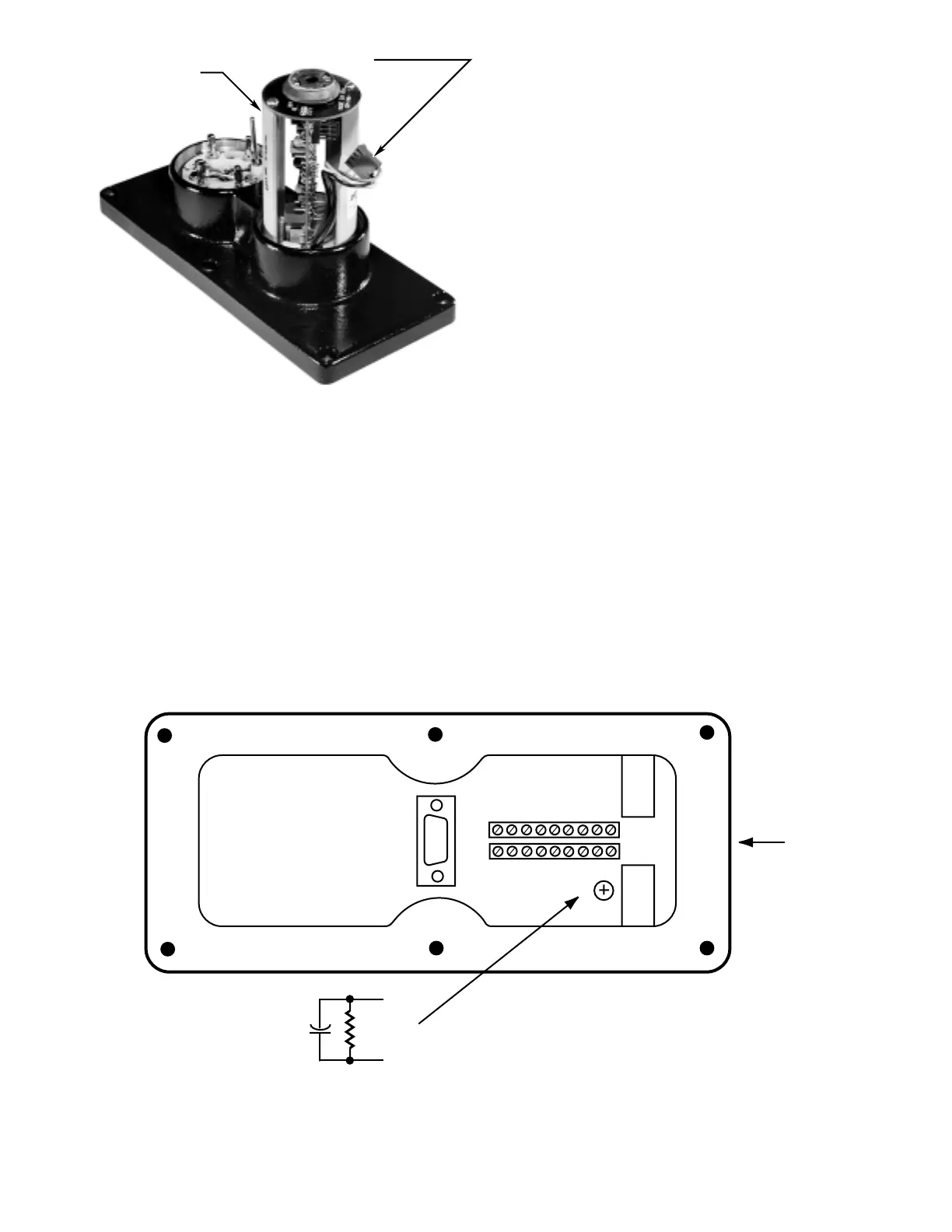
6. Install the new motherboard inside the junction
box and tighten the three screws. If not already
installed, a capacitor may be installed as shown
in Figure 18 to improve resistance to ground tran-
sients.
7. Re-connect all field wiring to the detector terminal
blocks.
8. Apply a small amount of lubricant to each of the
six screws on the junction box cover. Line up the
“D” connector on the junction box cover with the
connector on the motherboard, then re-install the
cover and tighten the six screws sufficiently to
ensure a metal-to-metal fit for explosion-proof and
watertight housing integrity.
15 95-8385
0.47
µ
f
400 VOLT
2 MEGOHM,
1/2 WATT
RESISTOR
CONDUIT
ENTRY
24 VDC
U7652 UV/IR DETECTOR WITH COVER REMOVED
R-C CIRCUIT
GND
GND
+–
–
NOTES
• THIS ENHANCEMENT IS INSTALLED ON ALL NEW U7652 DETECTORS. IT IS
RECOMMEDED THAT THIS ENHANCEMENT BE INSTALLED IN ALL EXISTING
MODELS TO PROVIDE INCREASED EMI PROTECTION.
• PARTS REQUIRED: 0.47 MICROFARAD, 400 VOLT CAPACITOR AND A
2 MEGOHM, 1/2 WATT RESISTOR.
• TERMINATE THE RESISTOR-CAPACITOR PARALLEL CIRCUIT BETWEEN THE DC
COMMON RETURN TERMINAL AND THE EARTH GROUND SCREW.
• ENSURE THAT ALL SOLDER CONNECTIONS AND BARE CONDUCTORS ARE
PROPERLY GROUNDED.
• IF USING GROUND FAULT MONITORING, CUT THE RESISTOR OUT.
A1976