MOUNTING AND WIRING PROCEDURE
The following procedure should be used for mounting and
wiring the detector. Refer to the following illustrations:
Figure 4 — Detector Junction Box with Cover
Removed (Terminal Blocks,
Programming Jumpers, Motherboard
Assembly)
Figure 5 — Detector Dimensions
Figure 6 — Swivel Mounting Bracket Dimensions
Figure 7 — U7652B Wiring Terminal
Configuration
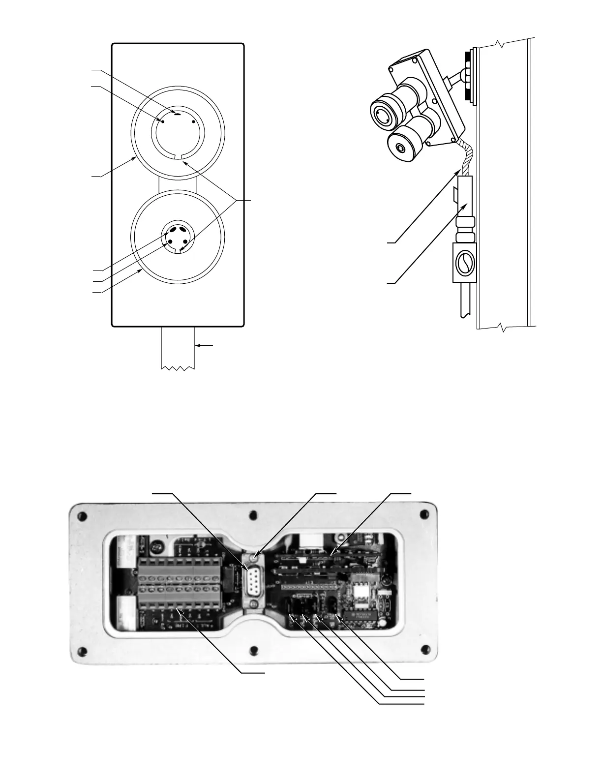
Figure 4—Detector Junction Box with Cover Removed (Terminal Blocks, Programming Jumpers, Motherboard Assembly)
6