4.1 95-862010
If the calibration sequence is aborted or not completed
successfully, the detector reverts back to the previous
calibration values and signals a calibration fault. If
a successful calibration cannot be performed, the
calibration fault can be cleared by activating the
magnetic switch on the gas detector for one second.
For help assessing when a fault has occurred see
Tables 3 and 4.
The calibration process can fail for the following causes:
•Zeroisoutofrange
•Spanisoutofrange
•Time-Out.
The time and date of calibration events are logged
in the GT3000’s non-volatile memory along with the
calibration outcome. Possible calibration scenarios
include the following:
•SuccessfulCalibration
•AbortedCalibration
•FailedCalibration
NOTE
The calibration procedure must be completed
within a ten minute period. If the calibration is not
completed, a calibration fault will be generated
and the previous calibration data will be used.
NOTE
To ensure reliable protection, it is important to
check and calibrate the detection system on a
regularly scheduled basis. The frequency of these
checks is determined by the requirements of the
particular installation – typically 30, 60, or 90 day
intervals, depending on the ambient conditions.
CALIBRATION PROCEDURE
1. Clean air must be present at the sensor prior
to initiating calibration. The use of bottled air is
recommended.
2. Calibration can be initiated in one of two ways:
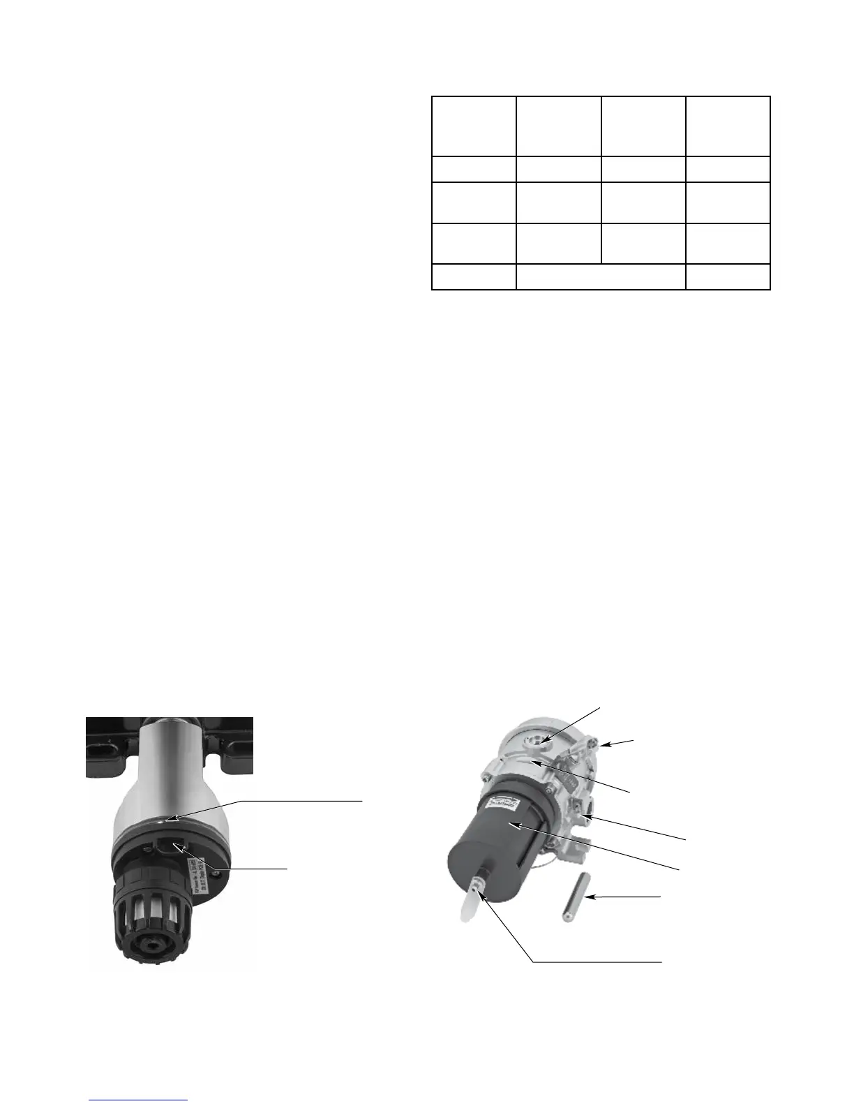
A. Hold the calibration magnet against the
designated location on the sensor module
(see Figures 10 and 11) until the green LED
turns off and the yellow LED turns on steady
(approximately one second).
B. Initiate calibration via the magnetic switches on
the UD20. Select Main Menu > Device Cal >
Calibration > Execute.
The UD20 indicates “Waiting for Zero.” The
transmitter immediately begins taking zero readings.
LED
PLACE MAGNET HERE
TO ACTIVATE INTERNAL
MAGNETIC SWITCH
A2452
Figure 10—Location of Magnetic Switch on GT3000 Detector
Table 3— GT3000 LEDs and 4-20 mA Output
During Various Status Conditions
Function
Green
LED
Yellow
LED
Analog
4-20 mA
Signal
Warm-up Off Steady On 3.5
Normal
Operation
Steady On Off 4-20
Fault
Condition
Off Steady On 3.5
Calibration See Table 1 3.8
CALIBRATION MAGNET
CALIBRATION NOZZLE
WEATHER BAFFLE
MULTICOLOR LED
HART COMMUNICATION PORT
(COVER INSTALLED)
PLACE CALIBRATION MAGNET
HERE TO ACTIVATE INTERNAL
REED SWITCH
C2058
EARTH GND LUG
Figure 11— Location of Magnetic Switch on PointWatch Eclipse