4.1 95-86205
WIRING CABLE REQUIREMENTS
Always use proper cabling type and diameter for input
power as well as output signal wiring. 22 to 14 AWG
shielded stranded copper wire is recommended.
Always install a properly sized, master power fuse or
breaker on the system power circuit.
For ambient temperatures below –10°C, use field wiring
suitable for the expected conditions. For ambient
temperatures above +60°C, use field wiring and cable
glands suitable for 15°C above the maximum expected
conditions.
NOTE
The use of shielded cable in conduit or shielded
armored cable is required. In applications where
the wiring is installed in conduit, dedicated
conduit is recommended. Avoid low frequency,
high voltage, and non-signaling conductors to
prevent nuisance EMI problems.
CaUtIon
The use of proper conduit installation techniques,
breathers, glands, and seals is required to prevent
water ingress and/or maintain the explosion-proof
rating.
JUNCTION BOX ENTRIES, PLUGS, & FITTINGS
WarnInG
All entries must contain appropriately rated
plugs or ttings. It is required that each plug or
tting be wrench-tightened to an appropriate
installation torque and meet the minimum thread
engagement requirements per the applicable
local standards, codes, and practices in order
to retain the dened ratings. PTFE sealant or
equivalent should be used on NPT threads.
WIRING PROCEDURE
UD20 with GT3000
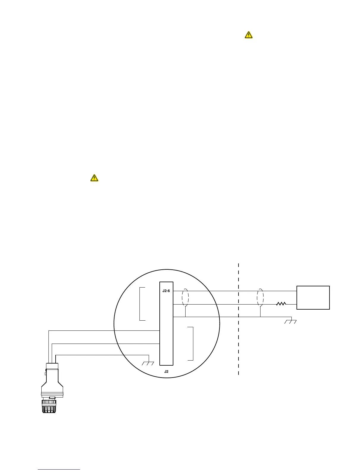
Refer to Figures 3 and 4 for wiring illustrations.
UD20 with PIRECL
No separate power lines are required for the UD20.
The device can be powered off the PIRECL detector in
a two-wire configuration. Figures 5 through 8 illustrate
the Eclipse wired to a UD20 with the 4-20 mA output
shown in various wiring schemes.
A 250 ohm, 3 watt HART resistor must be installed.
The current loop resistance must not exceed 440 ohms
for correct functioning of the detector mA output and
HART signal.
Figure 9 shows the UD20 with the optional Bartec Self-
Regulating Heating Cable System.
+
–
24 VDC
UD20 DISPLAY UNIT
B2406
J2-5
J2-4
J2-3
J2-2
J2-1
NOTE 1 CONNECT THE GREEN SENSOR LEAD TO THE CHASSIS GROUND LUG
ON THE INSIDE BOTTOM OF THE UD20 DISPLAY UNIT ENCLOSURE.
NOTE 2 250 OHM, 3 WATT RESISTOR REQUIRED (INCLUDED).
NOTE 3 EXTERNAL HART COMMUNICATION DEVICES CAN BE CONNECTED ACROSS
THE 250 OHM RESISTOR, ACROSS J2-5 AND J2-6, OR ACROSS J2-2 AND J2-3.
NOTE 4 JUNCTION BOX MUST BE ELECTRICALLY CONNECTED TO EARTH GROUND.
NOTE 5 GROUND THE SHIELD AT THE POWER SOURCE END ONLY.
SEE NOTES 2 AND 3
SEE NOTE 5
GT3000
GAS DETECTOR
+
+
–
–
SHIELD
SHIELD
SENSOR
LOOP
POWER
LOOP
BLACK
RED
GREEN
SEE NOTE 1
HAZARDOUS LOCATION NON-HAZARDOUS LOCATION
Figure 3—Basic Wiring for Explosion Proof UD20 with GT3000