L
Lynn GreenSep 23, 2025
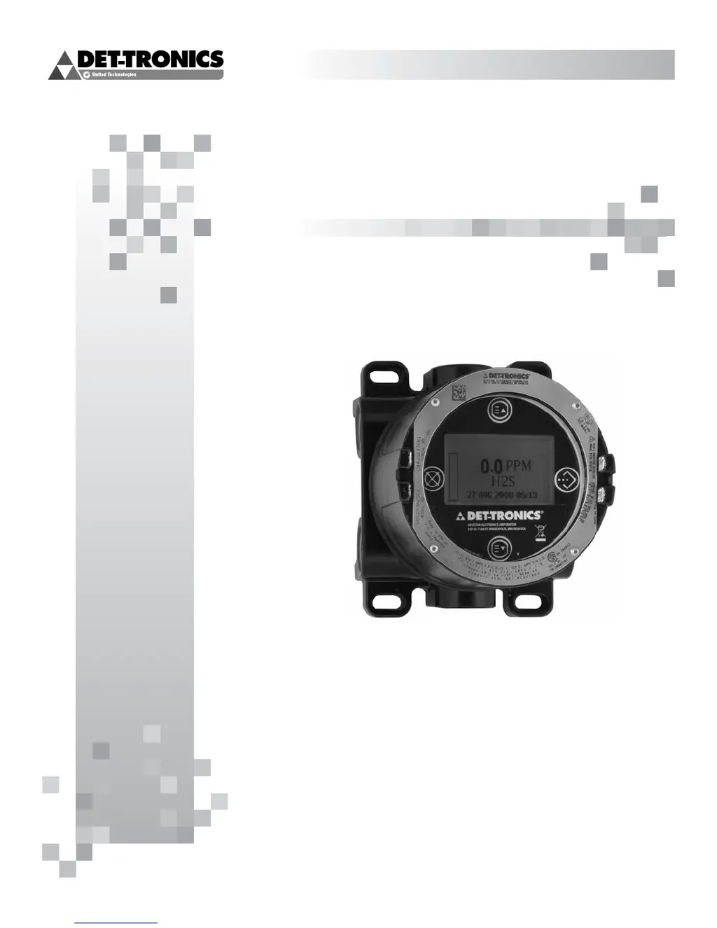
Why is my Det-Tronics Monitor showing an EE Fault?
- NnramosSep 23, 2025
An EE Fault indicates a fault in non-volatile memory. Power may have been interrupted while the device was updating its internal data logs. Recycle power.