13 95-86614.1
When the UD10 is used with a detector that supports
HART communication, the output of the detector should
be calibrated first.
HART Detector Signal Calibration
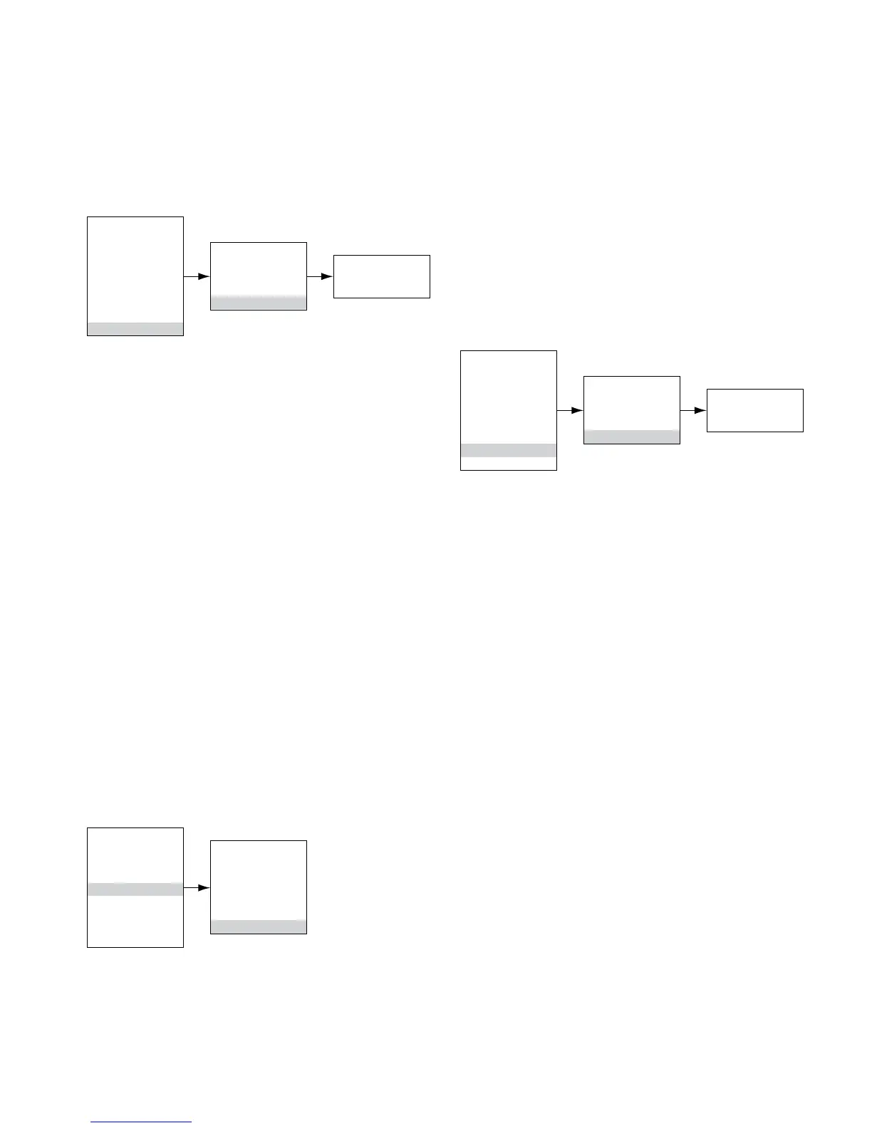
Navigate down the menu to Device Test > D/A (Digital
to Analog) Trim.
Main Menu
Process Vars
Display Status
Device Status
Display Setup
Device Setup
Device Cal
Display Test
Device Test
Device Test
Self Test
Response Test
Loop Test
D/A Trim
D/A Trim
Zero Trim
Gain Trim
Select Zero Trim. When this screen is entered, a
warning message is presented. Select ENTER to
continue. When the message “Connect Reference
Meter” is presented, install the current meter on the mA
line between the detector and UD10. Select ENTER
to continue. When the message “Set Input Current to
4mA?” is presented, select ENTER to begin the Zero
Trim function. The detector will now set its 4 mA output
value. If the value indicated on the current meter is not
4.00 mA, enter the measured value into the UD10 using
the Previous and Next switches. The UD10 calculates
and corrects for the difference between the actual and
entered values. When the current meter value is at the
desired 4.00 mA, select ENTER to accept the new zero
trim value.
Select Gain Trim. Follow the same procedure for gain/
span calibration.
UD10 Input Trim
When the UD10 is used with a detector that supports
HART communication, an automated process can be
used to trim the UD10 input. Navigate down the menu
to “Input Loop Cal”.
Main Menu
Process Vars
Display Status
Device Status
Display Setup
Device Setup
Device Cal
Display Test
Device Test
Display Setup
Alarm Setting
Mode Select
HART Option
RTC
RS485
Input Loop Cal
Upon entering Input Loop Cal, the UD10 commands
the detector to output 4 mA, and then automatically
calibrates its own input. The UD10 then commands the
detector to output 20 mA and subsequently calibrates
its own input.
If a non-HART detector is being used, the Input Loop
Cal may be performed with a mA current source or loop
calibrator connected to the UD10 Sensor Connector.
Follow the loop calibration instructions shown by the
UD10 for this procedure.
UD10 Output Trim
To calibrate the UD10 output loop, navigate down the
menu to Display Test > D/A Trim.
Main Menu
Process Vars
Display Status
Device Status
Display Setup
Device Setup
Device Cal
Display Test
Device Test
Display Test
Self Test
Response Test
Loop Test
D/A Trim
D/A Trim
Zero Trim
Gain Trim
Select Zero Trim. When this screen is entered, a warning
message is presented. Select ENTER to continue.
When the message “Connect Reference Meter” is
presented, install the current meter on the UD10 mA
output. Select ENTER to continue. When the message
“Set Output Current to 4mA?” is presented, select
ENTER to begin the Zero Trim function. The UD10
will now set its 4 mA output value. If the measured
value on the current meter is not 4.00 mA, enter the
measured value into the UD10 using the Previous and
Next switches. The UD10 calculates and corrects for
the difference between the actual and entered values.
When the current meter value is at the desired 4.00 mA,
select ENTER to accept the new zero trim value.
Select Gain Trim. Follow the same procedure for gain/
span calibration.