14 95-8661
4.1
OPTIONAL SYSTEM TESTS
The following tests are available for verifying proper
operation of various functions of the gas detection
system. The first three are accessed from the Display
Test screen. (A “Device Test” screen is available
for performing the same tests on HART enabled
detectors.)
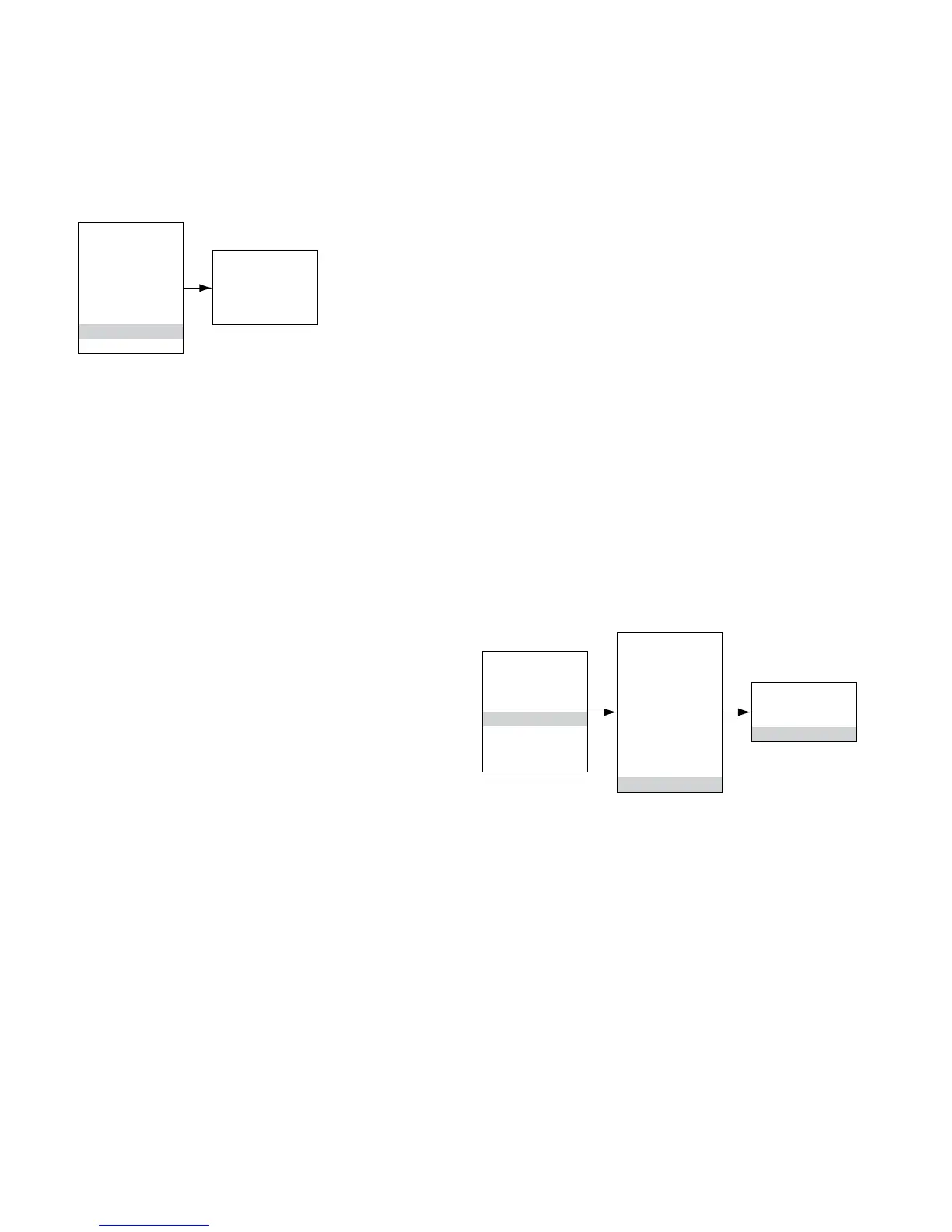
Main Menu
Process Vars
Display Status
Device Status
Display Setup
Device Setup
Device Cal
Display Test
Device Test
Display Test
Self Test
Response Test
Loop Test
D/A Trim
Self-Test
This test commands the UD10 to perform a fully
automatic internal test. At the completion of the test,
the UD10 will indicate a pass or fail.
Response Test
This test inhibits the UD10’s outputs, thereby providing
a means of testing the system by applying gas to the
detector without activating any alarms or affecting the
output.
Loop Test
This test temporarily forces the UD10’s 4-20 mA output
to a specific level. This is an easy way to test the
output signal of the UD10 for accuracy, to verify the
capabilities of the system, and to verify the input signal
of a receiver. To perform this test, connect a current
meter to the output loop. Navigate to Display Test and
select Loop Test, then follow the prompts on the UD10
Screen.
NOTE
If the Response Test and Loop Test are
not terminated by the operator, the test will
automatically time out after ten minutes and the
UD10 will return to normal operation.
Proof Test
A Proof Test (bump test) can be performed at any time
to verify proper operation and calibration of the system.
Since this test does not inhibit the UD10’s outputs, secure
any output devices prior to performing the test to prevent
unwanted actuation.
HISTORY
There are two separate histories, one for the display
and one for the detector (if available). Both will state
the number of hours that the unit has been operating,
and the highest and lowest recorded temperature (with
time and date stamp).
PASSWORD PROTECTION
The UD10 allows the use of a password for restricting
changes to configuration parameters and limiting
access to safety critical commands. The UD10 is
shipped from the factory with the password protection
(Write Protect) feature disabled.
The following are locked when Write Protect security is
enabled:
Alarm Setting screen – All options except “RST Latch
Alarms”
Mode Select screen – All options
HART Option – All options
RTC–AlloptionsexceptDisplayedY/N
Output Mode
Display Test screen – All options
To enable the Write Protect feature, navigate to the Write
Protect screen.
Select “Change State” to toggle between Enabled and
Disabled.
Select “Change Password” to enter a new password.
“Write Protect” indicates whether password protection
is Enabled or Disabled.
The default password is 1*******.
IMPORTANT
Take care not to lose the password. Future
changes cannot be made without a password.
Main Menu
Process Vars
Display Status
Device Status
Display Setup
Device Setup
Device Cal
Display Test
Display Setup
Alarm Setting
Mode Select
HART Option
RTC
RS485
Input Loop Cal
Contrast Contrl
Output Mode
Backlight Ctrl
Write Protect
Write Protect
Change State
Change Password
Write Protect xxx