4.1 95-8661M-1
AppenDix m
UD10 with MODEL 505 TRANSMITTER / CGS SENSOR
NOTE
For complete information regarding the Model 505 Transmitter, refer to instruction manual 95-8472.
WirinG
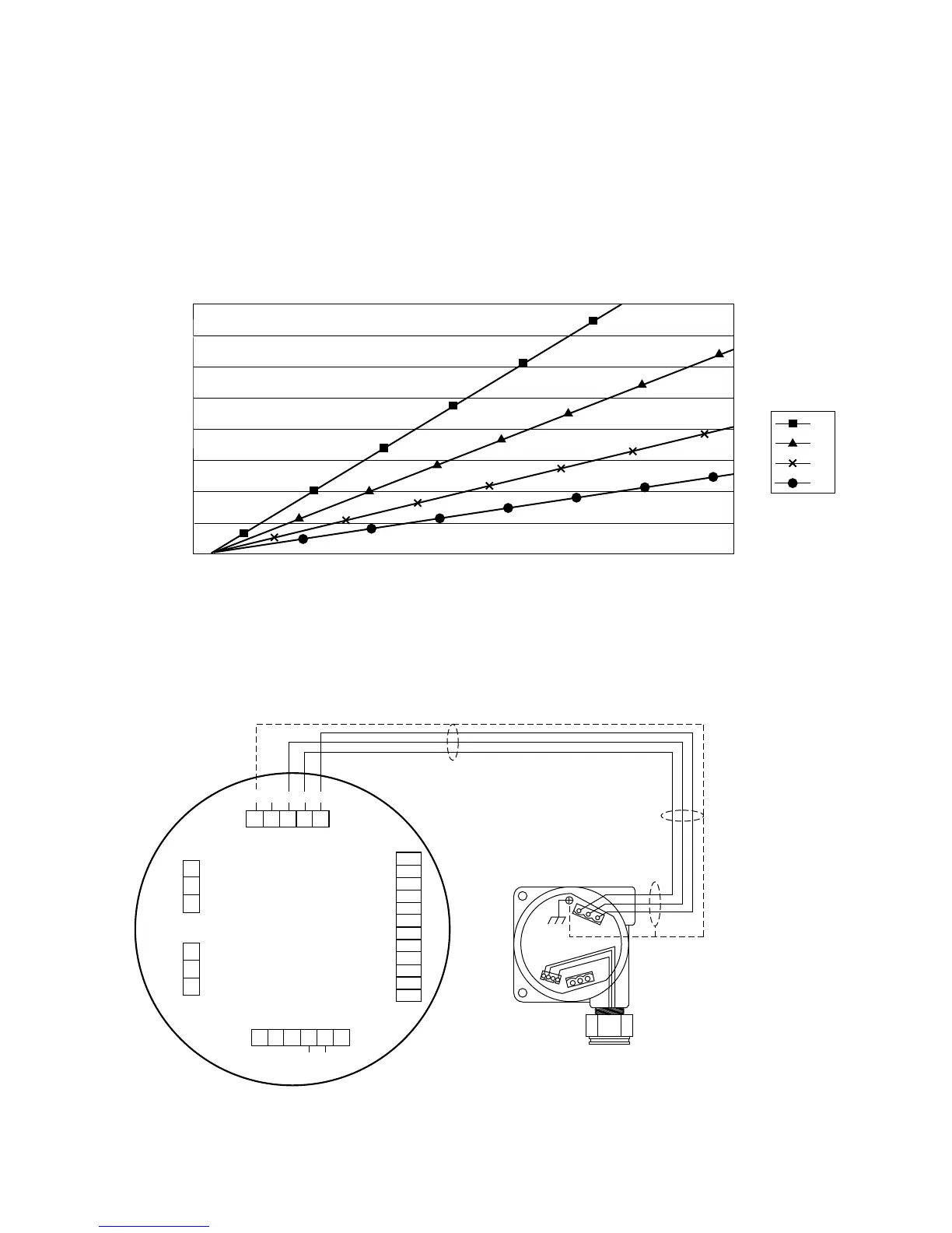
4000
3500
3000
2500
2000
1500
1000
500
0
18 19 20 21 22 23 24 25 26 27 28 29 30
Power Supply Voltage
Distance in ft.
UD10 with PIRECL/OPECL/Model 505/NTMOS
12
14
16
18
AWG
Wire Size
Notes: Maximum cable length from power source to UD10 is 2000 feet.
Maximum cable length from UD10 to detector/STB termination box is 2000 feet.
UD10
DISPLAY UNIT
MODEL 505 TRANSMITTER
CGS
SENSOR
B2424
–
SIG
RED
SENSOR
WHT
BLK
+
Sensor Connector
Power Supply Connector
Output Loop
Connector
MODBUS
Connector
Relay Connector
P1
J2
J3
J4
P2
4-20 mA +
4-20 mA –
SHIELD
COM
RS485 A
RS485 B
HIGH ALARM COM
HIGH ALARM NC
HIGH ALARM NO
AUX ALARM COM
AUX ALARM NC
AUX ALARM NO
LOW ALARM COM
LOW ALARM NC
LOW ALARM NO
FAULT COM
FAULT NC
FAULT NO
24 VDC –
24 VDC +
SHIELD
24 VDC –
24 VDC +
SHIELD
SHIELD
CALIBRATE
24 VDC –
4-20 mA
24 VDC +
P1-3
P1-2
P1-1
J2-3
J2-2
J2-1
J4-1
J4-2
J4-3
J4-4
J4-5
J4-6
J4-7
J4-8
J4-9
J4-10
J4-11
J4-12
J3-1
J3-2
J3-3
J3-4
J3-5
P2-6
P2-5
P2-4
P2-3
P2-2
P2-1
NOTE UD10 HOUSING MUST BE ELECTRICALLY
CONNECTED TO EARTH GROUND.
UD10 Wired to Model 505 Transmitter/CGS Sensor