15 95-86614.1
troubleshootinG
If a Fault condition is indicated on the UD10 faceplate,
the nature of the fault can be determined by using
the magnetic tool to navigate to the appropriate Fault
screen.
NOTE
Refer to the Menu in the appropriate Appendix
of this manual for the path to the proper Fault
screen.
Shortcut: From the main display screen, touch
the magnet to the “Previous” switch to go directly
to the Fault screen.
Example:
For a Display (UD10) related fault:
Main Menu > Display Status > Fault/Status > Fault
For a Device (Sensor) related fault:
Main Menu > Device Status > Fault/Status > Sensor Fault
When the active fault has been identified, refer to the
Troubleshooting Tables for a description of the fault and
suggested corrective action.
Refer to Table 3 for Display Faults and Table 4 for Device
Faults.
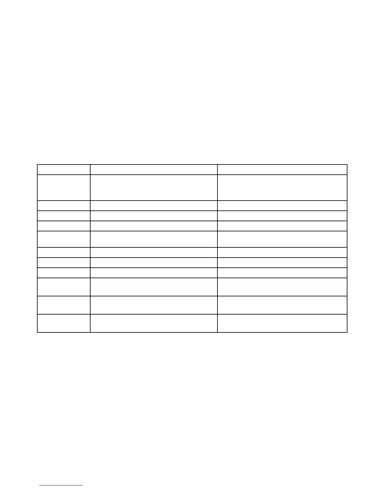
Display Faults Description Recommended Action
Input Loop FLT Fault in sensor or sensor loop
Check sensor wiring.
Calibrate sensor.
Ensure that sensor type matches conguration.
Output Loop FLT Fault in 4-20 mA output loop Check 4-20 mA loop wiring for shorts or opens.
EE Fault Fault in non-volatile memory Return to factory.
ADC Ref Fault ADC reference voltage too high or low Return to factory.
24V Fault Problem in 24 volt power supply or power wiring
Check power wiring and output voltage of power
supply.
Flash Fault FLASH memory Fault Return to factory.
RAM Fault Fault in volatile memory Return to factory.
WDT Fault Watchdog timer is non-functional Return to factory.
12V Fault 12 volt internal power supply out of tolerance
Check power source.
Return to factory.
5V Fault 5 volt internal power supply out of tolerance
Check power source.
Return to factory.
3V Fault 3 volt internal power supply out of tolerance
Check power source.
Return to factory.
Table 3—Troubleshooting Guide - Display Faults
Note: A fault condition will cause an oxygen detector to generate an alarm output as the decreasing 4-20 mA signal passes
through the alarm range.