H-2 95-8661
4.1
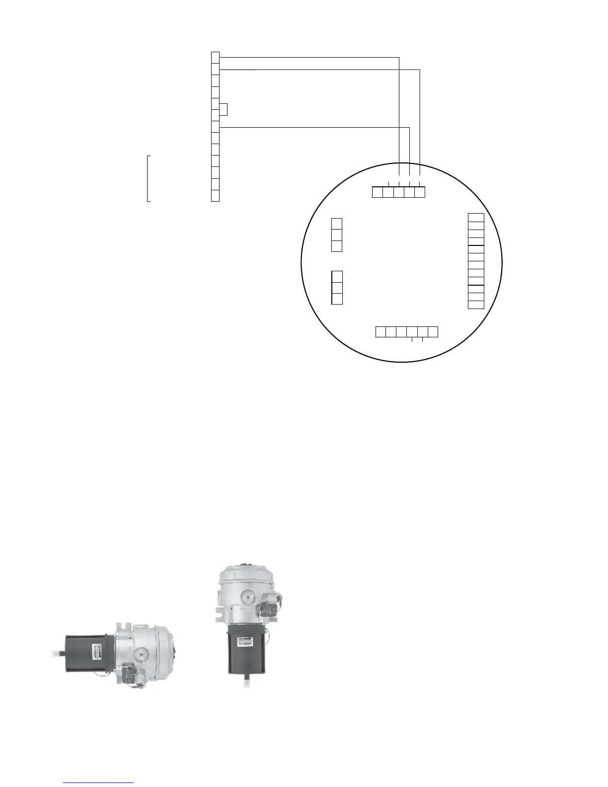
UD10 DISPLAY UNIT
24 VDC –
24 VDC –
24 VDC +
24 VDC +
CALIBRATE
4-20 MA +
4-20 MA –
RS-485 A
RS-485 B
RELAY POWER (RED)
FAULT (ORANGE)
LOW ALARM (WHITE)
HIGH ALARM (YELLOW)
WIRING TO OPTIONAL
RELAY BOARD
NO USER CONNECTION
1
2
3
4
5
6
7
8
9
10
11
12
13
MODEL PIRECL
C2404
BLACK
WHITE
RED
Sensor Connector
Power Supply Connector
Output Loop
Connector
MODBUS
Connector
Relay Connector
P1
J2
J3
J4
P2
4-20 mA +
4-20 mA –
SHIELD
COM
RS485 A
RS485 B
HIGH ALARM COM
HIGH ALARM NC
HIGH ALARM NO
AUX ALARM COM
AUX ALARM NC
AUX ALARM NO
LOW ALARM COM
LOW ALARM NC
LOW ALARM NO
FAULT COM
FAULT NC
FAULT NO
24 VDC –
24 VDC +
SHIELD
24 VDC –
24 VDC +
SHIELD
SHIELD
CALIBRATE
24 VDC –
4-20 mA
24 VDC +
P1-3
P1-2
P1-1
J2-3
J2-2
J2-1
J4-1
J4-2
J4-3
J4-4
J4-5
J4-6
J4-7
J4-8
J4-9
J4-10
J4-11
J4-12
J3-1
J3-2
J3-3
J3-4
J3-5
P2-6
P2-5
P2-4
P2-3
P2-2
P2-1
NOTE 1 INTERNAL JUMPER REQUIRED FOR
NON-ISOLATED CURRENT OUTPUT
(SINGLE POWER SUPPLY).
NOTE 2 UD10 HOUSING MUST BE ELECTRICALLY
CONNECTED TO EARTH GROUND.
1
Model PIRECL Wired Directly to UD10
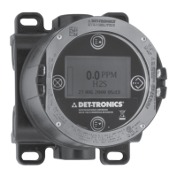
orientAtion
It is highly recommended that the PIRECL be
installed in the horizontal position. The detector
is not position-sensitive in terms of its ability to detect
gas. However, the weather baffle assembly provides
superior performance when the PIRECL is installed
with the baffle in a horizontal position.
CORRECT
INCORRECT