4.1 J-1 95-8661
AppenDix J
UD10 with NTMOS H
2
S SENSOR
NOTE
For complete information regarding the NTMOS Gas Detector, refer to instruction manual 95-8604.
WirinG
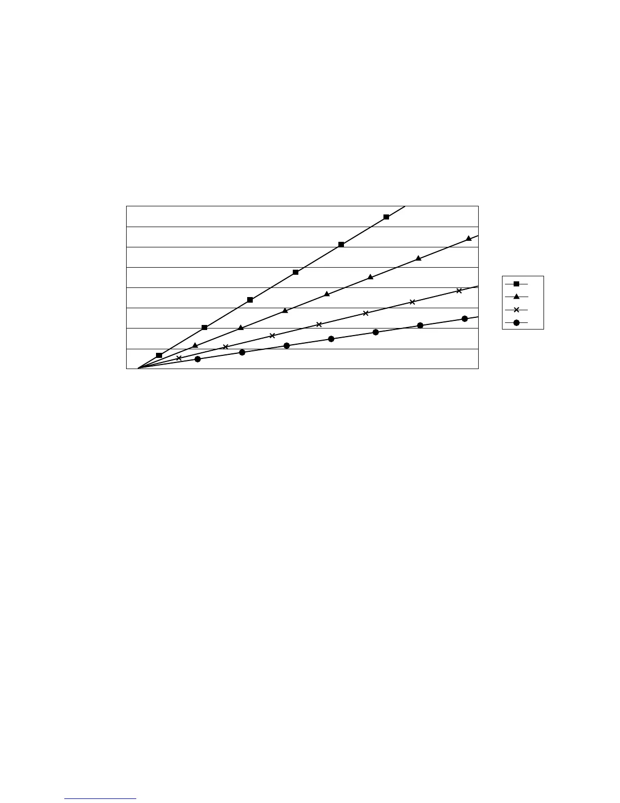
4000
3500
3000
2500
2000
1500
1000
500
0
18 19 20 21 22 23 24 25 26 27 28 29 30
Power Supply Voltage
Distance in ft.
UD10 with PIRECL/OPECL/Model 505/NTMOS
12
14
16
18
AWG
Wire Size
Notes: Maximum cable length from power source to UD10 is 2000 feet.
Maximum cable length from UD10 to detector/STB termination box is 2000 feet.
instAllAtion notes
NOTE
Never use silicone grease with the NTMOS
sensor.
NOTE
A junction box spacer or standoff may be used to
increase the distance between the device and the
mounting surface, thereby facilitating installation
and use of the ampoule calibrator.
NOTE
For non-HART applications, the NTMOS sensor
can be wired to the Sensor Connector terminals
(J3) on the UD10 module. If HART communication
will be used, the NTMOS sensor must be wired to
the optional NTMOS Connector Board, located on
the inside bottom of the UD10 housing. Refer to
the appropriate wiring diagram.