4.1 95-86204
IDENTIFICATION OF DETECTOR MOUNTING
LOCATIONS
Identification of the most likely leak sources and
leak accumulation areas is typically the first step in
identifying the best detector mounting locations. In
addition, identification of air current / wind patterns
within the protected area is useful in predicting gas leak
dispersion behavior. This information should be used to
identify optimum sensor installation points.
If the vapor of interest is lighter than air, place the sensor
above the potential gas leak. Place the sensor close to
the floor for gases that are heavier than air. Note that air
currents may cause a gas that is slightly heavier than
air to rise under some conditions. Heated gases may
also exhibit the same phenomenon.
The most effective number and placement of detectors
varies depending on the conditions at the job site. The
individual designing the installation must often rely on
experience and common sense to determine the detector
quantity and best locations to adequately protect the
area. Note that it is typically advantageous to locate
detectors where they are accessible for maintenance.
Locations near excessive heat or vibration sources
should be avoided if possible.
Final suitability of possible gas detector locations
should be verified by a job site survey.
For locations with expected periodic temperature
conditions from –20°C to –40°C, a certified heater jacket
system must be applied, and the installation should be
accepted by the local authority having jurisdiction.
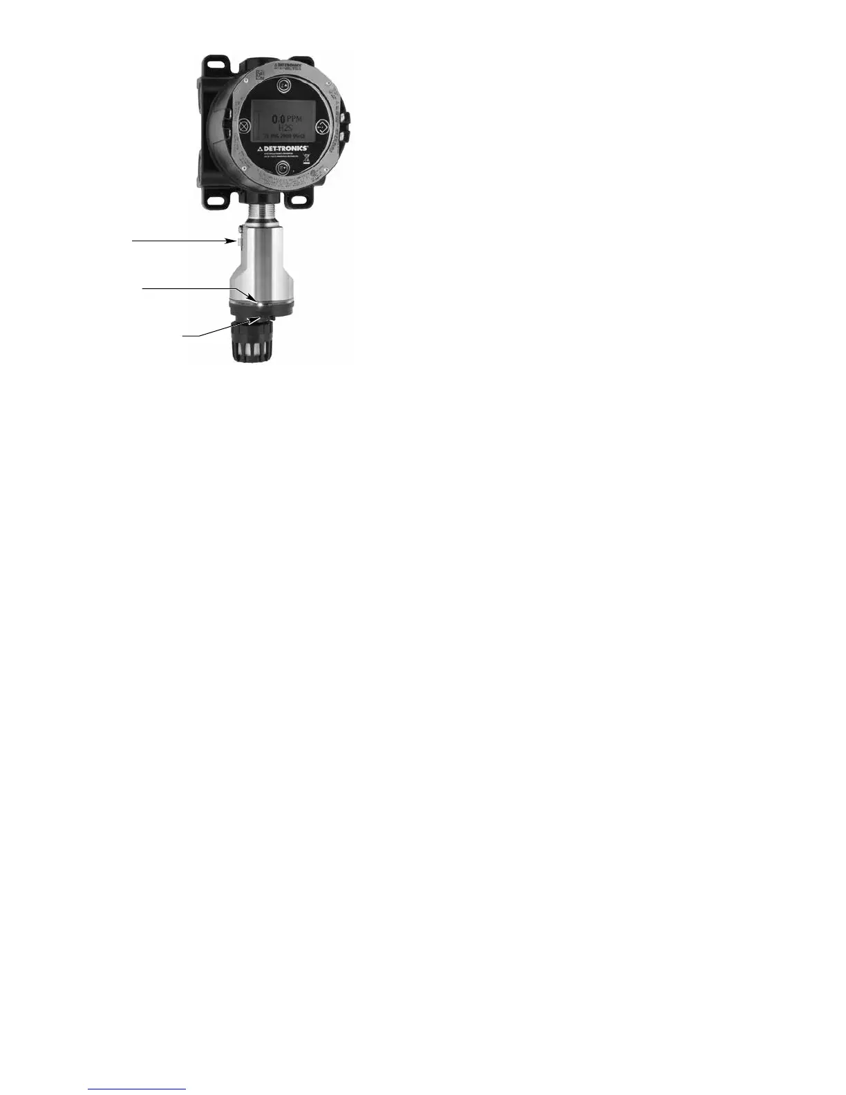
DEVICE MOUNTING ORIENTATION
The GT3000 detector must be mounted in a vertical
position only, with the sensor pointing down. See Figure
2. For details on mounting the PIRECL detector, refer to
manual number 95-8526.
Im porta n t
The GT3000 must be oriented with the LEDs
facing forward so they are easily visible to
personnel within the area. To ensure correct
orientation (the LEDs are not visible when power
is off), position the GND lug on the left hand side
and the calibration notch to the front. Note that the
LEDs are located directly above the calibration
notch.
SENSOR SEPARATION
Det-Tronics sensor termination boxes (Model STBs)
enable the installation of the GT3000 separately from
the UD20 Universal Display Unit. Two-conductor
shielded cable is required to prevent possible nuisance
EMI/RFI.
The PIRECL contains its own termination box for sensor
separation from the UD20.
The maximum cable length between the termination
box and the UD20 is 2000 ft.
WirinG
POWER SUPPLY REQUIREMENTS
Calculate the total gas detection system power
consumption rate in watts from cold start-up. Select a
power supply with adequate capability for the calculated
load. Ensure that the selected power supply provides
regulated and filtered 24 Vdc output power for the
entire system. If a back-up power system is required,
a float-type battery charging system is recommended.
If an existing source of 24 Vdc power is being utilized,
verify that system requirements are met.
NOTE
The UD20 and GT3000/PIRECL communicate
using HART protocol, which requires a power
supply with low noise levels for proper operation.
(For detailed information regarding power supply
specications, refer to the HART Communication
Foundation’s document “FSK Physical Layer
Specication” HCF_SPEC-54.)
GREEN LED
CALIBRATION NOTCH
B2436
GND LUG
Figure 2—Correct Mounting Orientation