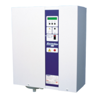
ElectroVap RTH-V2
44
Pictures and values are not contractual - The devices may be subject to changes without notice
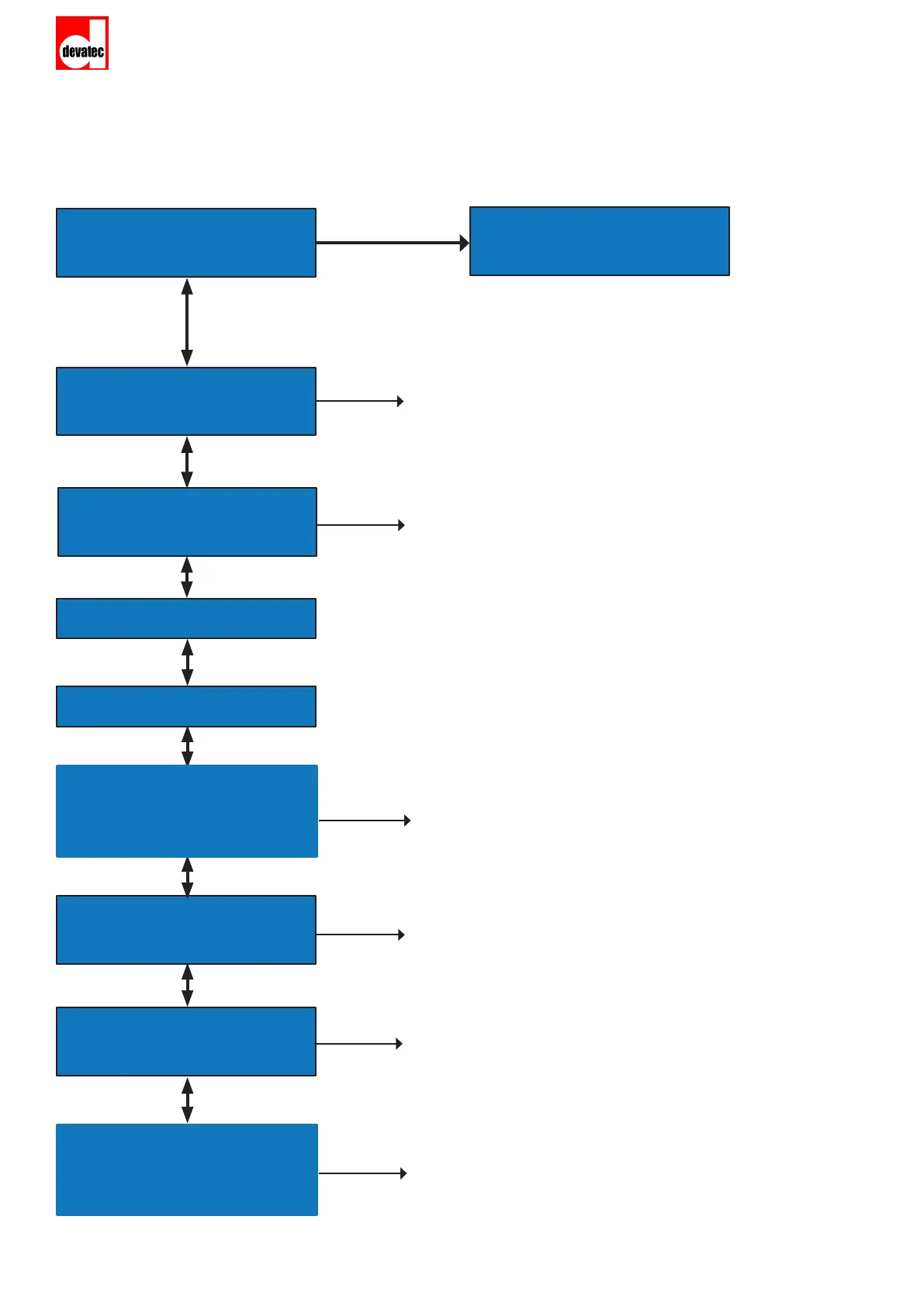
5.3 CONTROL SYSTEM MENU
NS HLS CTRL D%
X X X X
CONTROL
SYSTEM
K FV DV LV
X X X X
HUMIDIFIER
CONFIGURATION
K : Contactor 0: o / 1 on
FV : Fill Valve 0 closed / 1 opened
DV : Drain Valve 0 closed / 1 opened
LV : Levels 0: Low level, lling
1 : lling + production
2 : pulse lling
3 : stop lling
A1: Alarm Status A1 0: no fault/ 1: fault
Water temperature for right/left tank (NC displayed if the
sensor is not connected)
TX COM 1
RX COM 1
A2 LV FV TIMER
X X X X
A3 LV FV TIMER
X X X X
A2: Alarm status A2 0: no fault/ 1: fault
LV: Levels 0, 1, 2, et 3
FV: Fill Valve 0: closed/ 1: opened
TIMER: Timeout Alarm A2
A3: Alarm status A2 0: no fault/ 1: fault
LV: Levels 0, 1, 2, et 3
FV: Fill Valve 0: closed/ 1: opened
TIMER: Timeout Alarm A3
NS : Network Bus 0: Stop / 1 Run
HLS : High Limit Switch 0 opened / 1 closed
CTRL : Control signal
D% : Demand (%)
A1: L XXX°C XXX°F
X R XXX°C XXX°F
A1: L XXX°C XXX°F
X R XXX°C XXX°F
A4: Alarm Status A1 0: no fault/ 1: fault
Water temperature for right/left tank (NC displayed if the
sensor is not connected)