10
System overview
The DEVIreg™ 850 can handle up to 2 independent areas, in any of the following
combinations:
t 4JOHMFSPPGTZTUFN
(1 system, 1-4 roof sensors)
t 4JOHMFHSPVOETZTUFN
(1 system, 1-4 roof sensors)
t HSPVOETZTUFNBOESPPGTZTUFN (combi system)
(2 systems, 2-4 sensors total, minimum 1 sensor per system)
t SPPGTZTUFNT (dual system)
(2 systems, 2-4 sensors total, minimum 1 sensor per system)
t HSPVOETZTUFNT (dual system)
(2 systems, 2-4 sensors total, minimum 1 sensor per system)
When more than 1 area is controlled by the DEVIreg™ 850 system, it is also possible to
prioritize the areas. Prioritizing makes it possible to operate 2 areas, even if the needed
power for 2 areas is not present.
A typical ice and snow melting system consists of:
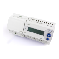
t %&7*SFH
Only 1 DEVIreg™ 850 is allowed on the DEVIbus™
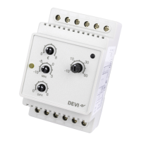
t 1PXFSTVQQMZ
More power supplies can be connected in parallel (if needed)
Be aware of maximum number of sensors on each power supply
(Refer to Technical Specication for power demand of sensors)
t (SPVOEBOEPSSPPGTFOTPST
Be aware of maximum number and cable length of sensors on each power supply
(Refer to sensor manual for a more detailed description)
Installer Manual