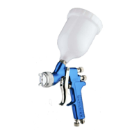
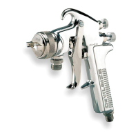
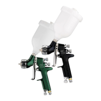
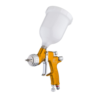
SB-2-630 Page 3
Fluid Tip (Ref. No. 5) Fluid Tip Fluid Tip
Computer Size Size
Part No. No. (in.) (mm) Applications
FLG-302-13K* 690032 0.051 1.3 Stains, lacquers, basecoats, clears.
FLG-302-15K 690018 0.059 1.5 General purpose, light to medium viscosity material.
FLG-302-18K* 690033 0.070 1.8 Primers and medium viscosity materials.
FLG-302-22K* 690019 0.086 2.2 Latex and heavy materials.
*Optional tips for FLG3 guns available as service parts only.
Chart 2 – Fluid Tips
Air Cap (Ref. No. 2)
Computer
Part No. No. Application
FLG-1-1 690000 Conventional
Chart 1 – Air Caps
CLEANING
Air Pressure: Always clean with reduced air pressure. An air
pressure no greater than 15 to 20 psi will allow quick and thorough
cleaning of the cup and gun and at the same time will minimize the
amount of solvent atomized into the air.
Cleaning Procedure:
1. Empty paint from cup and add small amount of clean solvent.
The amount required will vary with different coatings and
solvents.
2. Shake cup to wash down inside surfaces. Then spray solvent
at low air pressure (15-20 psi) to flush out fluid passages.
3. Pour out solvent and add same amount of clean solvent.
4. Again, shake cup and respray to flush out fluid passages.
5. Wipe gun exterior with a solvent dampened cloth. Never
completely immerse gun in solvent as this is detrimental to
the lubricants and packings.
6. To clean air cap and fluid tip, brush exterior with a stiff bristle
brush. If necessary to clean cap holes, use a broom straw or
toothpick if possible. If a wire or hard instrument is used,
extreme care must be used to prevent scratching or burring of
the holes which will cause a distorted spray pattern.
7. Since all materials in the cup are highly solvent resistant, the
cup assembly may be immersed for cleaning. Immersion
should not exceed 24 hours. The use of paint strippers should
be avoided because strippers will affect the aluminum as well
as other nonmetallic components. If the lid gasket has become
swollen from prolonged exposure to solvents, it will return to
its original size without loss of properties when allowed to dry.
8. For routine cleaning, it is not necessary to remove the lid
gasket.
9. Pry the splash shield loose from the bottom of the lid and wipe
clean with a solvent soaked rag. Reinstall.
PREVENTIVE MAINTENANCE
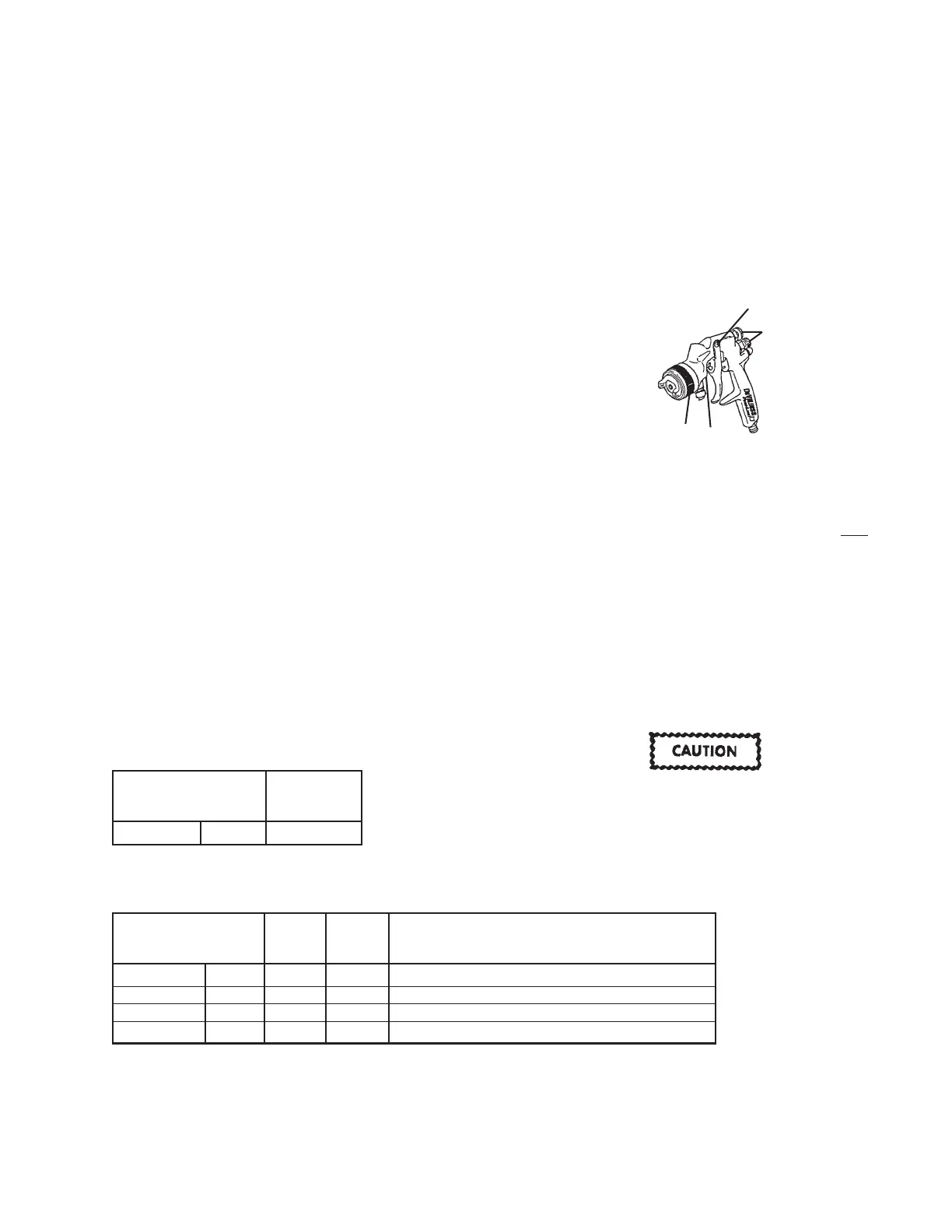
Spray Gun Lubrication
Daily, apply a drop of SSL-10 spray gun lube at trigger bearing
stud (21) and the stem of the air valve (14). The shank of the fluid
needle (11) where it enters the packing nut (24) should also be
oiled. The fluid needle packing (23) should be kept soft and
pliable by periodic lubrication. Make sure the baffle (6) and
retaining ring (1) threads are clean and free of foreign matter.
Before assembling retaining ring to baffle, clean the threads
thoroughly, then add two drops of SSL-10 spray gun lube to
threads. The fluid needle spring (12) and air valve spring (15)
should be coated with a very light grease, making sure that any
excess grease will not clog the air passages. For best results,
lubricate the points indicated, daily.
PARTS REPLACEMENT
Note
When replacing the fluid tip or fluid needle, replace
both
at the same time. Using worn parts can cause fluid leak-
age. Also, replace the needle packing and fluid tip seal at
this time. Lightly lubricate the threads of the fluid tip
before reassembling. Torque to 15-20 ft-lbs. Do not over-
tighten the fluid tip.
The tip size is stamped on the hex of the fluid tip (#3). The fluid tip
part number and tip size are also stamped around the outside of
the fluid tip.
See Chart 2 for selecting the proper size fluid tip for the material
you are spraying.
To prevent damage to the fluid tip (3) or fluid needle (11),
be sure to either 1) pull the trigger and hold while tight-
ening or loosening the fluid tip or 2) remove fluid needle
adjusting screw (13) to relieve spring pressure against
needle collar.
A
C
B
D
A. Trigger Points
B. Packing
C. Adjusting Valves
D. Baffle/Air Cap Threads