SERVICE BULLETIN
SB-2-775-A
Replaces SB-2-775
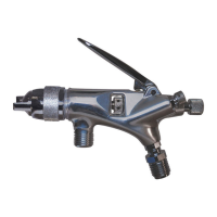
Gun Repair Kit FLG4-488-K
IMPORTANT: Before using this equip-
ment, read all safety precautions on
page 2 and instructions. Keep for
future use.
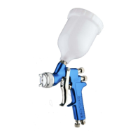
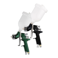
GUN DESCRIPTION
The FLG4 is a light weight, anodized alumi-
num, general purpose gravity feed spray
gun designed for use in various types of
spraying applications. Various models are
available to handle HVLP, water based, and
solvent based spraying applications.
These guns are sold with either a 900 cc
aluminum cup (702576) or a 20 oz. Acetal
cup (GFC-501). These guns are suitable
for use with water based materials ONLY
if used with a Acetal cup, or with a
disposable cup system.
Halogenated hydrocarbon sol-
vents - for example; 1, 1, 1- trichlo-
roethane and methylene chloride
- can chemically react with the
aluminum in this gun and cause
an explosion hazard. Read the
label or data sheet for the material
you intend to spray. Do not use
spray materials containing these
solvents with this spray gun.
IMPORTANT: This gun may be used with
most common coating and finishing
materials. It is designed for use with
mildly corrosive and non-abrasive materials.
If used with other high corrosive or
abrasive materials, it must be expected
that frequent and thorough cleaning will
be required and the necessity for replace-
ment of parts will be increased.
HVLP MODELS:
HVLP models of this gun were manufactured
to provide maximum transfer efficiency by
limiting air cap pressure to 10 psi (complies
with rules issued by SCAQMD and other air
quality authorities).
HVLP models of this gun will produce
approximately 10 psi cap pressure at 23 psi
gun inlet pressure, as measured at the gun
inlet. An air cap test kit (see Accessories)
should be used to insure 10 psi cap pressure
is not exceeded.
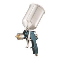
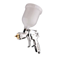
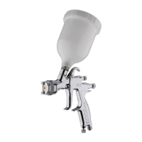
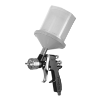
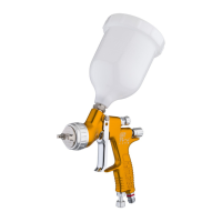
FLG4 GRAVITY FEED SPRAY GUN AND CUP
The No. 3 (HVLP) air cap requires a 13 cfm
air supply at the gun inlet of 23 psi max.,
measured with the trigger pulled.
CUP DESCRIPTIONS
702576 – 900 cc Aluminum Cup
The cup is constructed from durable
aluminum to provide trouble-free operation.
The cup insert is electroless nickel plated
brass. The disposable cup lid is recyclable
and is constructed with recycled polyeth-
ylene. The lid has a unique drip check to
prevent paint from dripping out of the vent
in the lid.
190252 (GFC-501) – 20 oz. Acetal Cup
The cup and screw-on lid are constructed
from durable Acetal to provide trouble-free
operation. The lid has a unique drip check
to prevent paint from dripping out of the
vent in the lid. The cup also has a high
grade stainless steel connector which is
compatible with water based and all com-
mon coating materials.
ASSEMBLY OF CUP TO GUN
This gun has been assembled with a cup
gasket (12) (blue) in the fluid inlet of the
gun body. Place filter (15) in the cup outlet
at this time if desired. See Cup Drawing on
page 4. Assemble cup to gun and tighten
hand tight.
INSTALLATION
Note
Protective coating and rust inhibi-
tors have been used to keep the
gun in good condition prior to
shipment. Before using the gun,
flush it with solvents so that these
materials will be removed from
fluid passages.
For maximum transfer efficiency, do not
use more pressure than is necessary to
atomize the material being applied.
Connect the gun to a clean, moisture and oil
free air supply using a hose size of at least
5/16" I.D. hose. Do not use 1/4" I.D. hose.
(25' x 1/4" hose at 18 CFM has a pressure
loss of 25 psi. 25' x 5/16" hose at 18 CFM
has a pressure loss of 8 psi.)
(continued on page 3)
Note
Depending on hose length, larger
I.D. hose may be required. Install a
DeVilbiss air adjusting valve at the
gun handle and air cap test kit over
tip. When gun is triggered on, ad-
just regulated pressure to desired
setting to provide a maximum of
10 psi at the air cap. Do not use
more pressure than is necessary
to atomize the material being ap-
plied. Excess pressure will create
additional overspray and reduce
transfer efficiency.
Note
If quick connects are required,
use only high flow quick connects
approved for HVLP use, such as
DeVilbiss HC-4419 and HC-4719.
Other types will not flow enough
air for proper gun operation.
Note
If an air adjusting valve is used
at the gun inlet, use a DeVilbiss
model. Some competitive
adjusting valves have significant
pressure drop that can adversely
affect spray performance.
DeVilbiss air adjusting valves
have minimal pressure drop,
which is important for HVLP
spraying.
OPERATION
Mix, prepare and strain the material to
be sprayed according to the paint maufac-
turer's instructions.
FILLING WITH PAINT
Fill the cup with paint to the full mark (702576)
or to bottom of the threads (GFC-501). Do
not overfill.
INSTALLING THE LID
Place plastic lid on the top of the cup, and
push in the center of the lid to assemble lid
(702576) or screw lid onto cup (GFC-501).
Fold vent cap and push onto center portion
of lid (if vent cap is not already assembled).
ENGLISH