Introduction 12
devolo Magic 2 LANDINrail
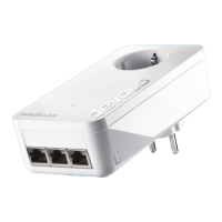
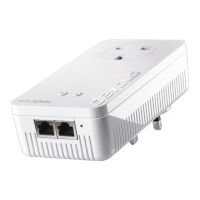
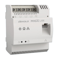
2.3 The devolo Magic adapter fea-
tures
b Four line connections
b One Gigabit network connection
b Three indicator lights
a Power
a PLC
a Ethernet
The LED status display can be disabled. You can
find more information about this in Chapter 5
Configuration or in the product manual for the
devolo Cockpit software available online at
www.devolo.com/cockpit
.
b One PLC button
b One reset button
2.3.1Line connections
This is where you connect the conductors to the
corresponding line connections.
Single-phase connection: Neutral conductors and
external conductors are connected to terminals N
and L1.
Three-phase connection: Neutral conductors and
three external conductors are connected to termi-
nals N, L1, L2 and L3. The device is supplied with
power via terminals N and L1.
PE connection: Connecting the earth wire to the
PE terminal
The permitted conductor cross-section for
connection to the terminals is 0.18 mm² to 6 mm².
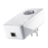
2.3.2Network connection
You can use the network connection (Fig. 2) on the
devolo Magic adapter to connect it to your inter-
net router using standard network cables.