11
ENGLISH
any of the accuracy checks listed in this manual, follow
theseguidelines:
• Use the largest area/distance possible, closest to the
operating distance. The greater the area/distance, the
easier to measure the accuracy of thelaser.
• Place the laser on asmooth, flat, stable surface that is
level in bothdirections.
• Mark the center of the laserbeam.
Using the Laser
Leveling the Laser
As long as the laser is properly calibrated, the laser is
self-leveling. Each laser is calibrated at the factory to find
level as long as it is positioned on a flat surface within
average ± 4° of level. No manual adjustments arerequired.
If the laser has been tilted so much that it cannot self-level
(> 4°), the laser beam will flash. There are two flashing
sequences associated with the out-of-levelcondition.
Using the Pivot Bracket (Fig.I, J, M)
The laser has a magnetic pivot bracket
6
permanently
attached to theunit.
WARNING: Position the laser and/or wall mount on
astable surface. Serious personal injury or damage to
the laser may result if the laserfalls.
• The bracket has a keyhole slot
7
so it can be hung from
a nail or screw on any kind ofsurface.
• The bracket has magnets
12
which allow the unit to
be mounted to most upright surfaces made of steel or
iron. Common examples of suitable surfaces include
steel framing studs, steel door frames, and structural
steel beams. Before attaching the pivot bracket against a
stud
13
, place the Metal Enhancement Plate
14
on the
opposite side of thestud.
• The bracket has tripod threads
11
on the bottom, so it
can be mounted to a tripod and placed where need.
Field Calibration Check
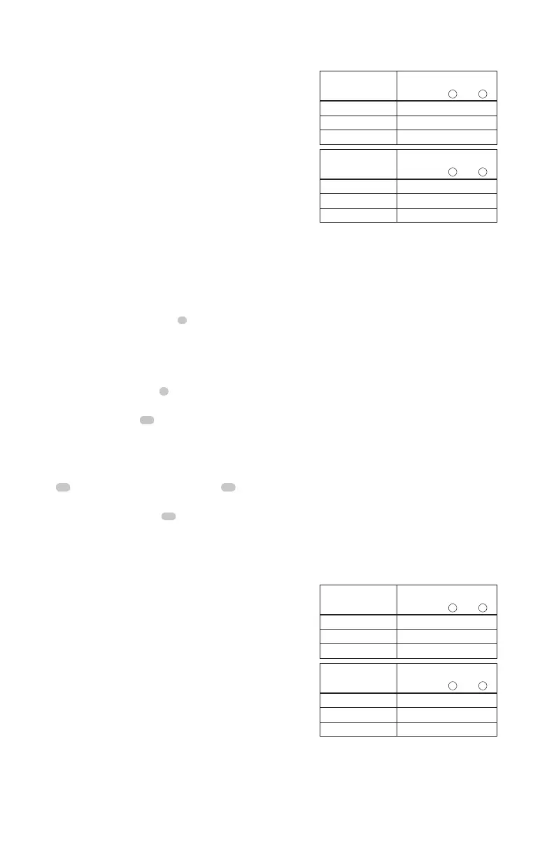
Checking Accuracy – Horizontal Beam,
Scan Direction (Fig. F)
Checking the horizontal scan calibration of the laser requires
two walls at least 30' (9 m) apart. It is important to conduct
a calibration check using a distance no shorter than the
distance of the applications for which the tool will beused.
1. Attach the laser to a wall using its pivot bracket. Make
sure the laser is facing straightahead.
2. Turn on the laser's horizontal beam and pivot the laser
approximately 45˚ so that the rightmost end of the laser
line is striking the opposing wall at a distance of at least
30' (9 m). Mark the center of the beam (a).
3. Pivot the laser approximately 90˚ to bring the leftmost
end of the laser line around to the mark made in Step 2.
Mark the center of the beam (b).
4. Measure the vertical distance between themarks.
• If the measurement is greater than the values shown
below, the laser must be serviced at an authorized
servicecenter.
Distance
Between Walls
Allowable Distance
Between
a
and
b
30' 1/8"
40' 5/32"
50' 7/32"
Distance
Between Walls
Allowable Distance
Between
a
and
b
9.0 m 3.1 mm
12.0 m 4.2 mm
15.0 m 5.2 mm
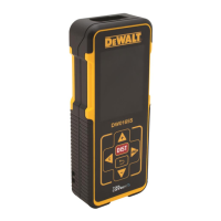
Checking Accuracy – Horizontal Beam,
Pitch Direction (Fig. G)
Checking the horizontal pitch calibration of the laser requires
a single wall at least 30' (9 m) long. It is important to conduct
a calibration check using a distance no shorter than the
distance of the applications for which the tool will beused.
1. Attach the laser to one end of a wall using its
pivotbracket.
2. Turn on the laser's horizontal beam and pivot the laser
toward the opposite end of the wall and approximately
parallel to the adjacentwall.
3. Mark the center of the beam at two locations (a, b) at
least 30' (9 m)apart.
4. Reposition the laser to the opposite end of thewall.
5. Turn on the laser's horizontal beam and pivot the laser
back toward the first end of the wall and approximately
parallel to the adjacentwall.
6. Adjust the height of the laser so that the center of the
beam is aligned with the nearest mark (b).
7. Mark the center of the beam (c) directly above or below
the farthest mark (a).
8. Measure the distance between these two marks(a,c).
• If the measurement is greater than the values shown
below, the laser must be serviced at an authorized
servicecenter.
Distance
Between Walls
Allowable Distance
Between
a
and
c
30' 1/4"
40' 5/16"
50' 13/32"
Distance
Between Walls
Allowable Distance
Between
a
and
c
9.0 m 6.2 mm
12.0 m 8.3 mm
15.0 m 10.4 mm
Checking Accuracy – Vertical Beam (Fig. H)
Checking the vertical (plumb) calibration of the laser can be
most accurately done when there is a substantial amount of
vertical height available, ideally 20' (6m), with one person
on the floor positioning the laser and another person near
a ceiling to mark the position of the beam. It is important