ENGLISH
24
E-Clutch® and Service Indicator LEDs (Fig. A)
Your rotary hammer has two LEDs
10
, indicating the
E-Clutch® (ADC) function and a service indicator. Refer to
the table for more information on LEDfunctionality.
LED Function Description
Red
(flashing)
Lock-on/Service
The red indicator LED
10
lights
up if the lock-on button
8
is used
in any mode except the chipping
mode or if there is a fault with
the tool or the brushes have
completely worn out
Red
(permanently on)
E-Clutch®
E-Clutch® is engaged.
Yellow
(permanently on)
Brush Service
The yellow brushwear indicator
LED
10
lights up when the
carbon brushes are nearly worn
out, indicating that the tool needs
servicing within the next 8 hours
ofuse.
Operation Modes (Fig. E)
WARNING: Do not select the operating mode when
the tool isrunning.
CAUTION: Never use in Rotary Drilling or Rotary
Hammering mode with a chisel bit in the bit holder.
Personal injury and damage to the the tool mayresult.
Your tool is equipped with a mode selector dial
4
to
selectthe mode appropriate to desiredoperation.
Symbol Mode Application
Rotary
Hammering
Drilling into concrete
and masonry
Hammering
only
Lightchipping
Bit Adjustment
Chisel bit position
adjustment
To select an operating mode
1. Rotate the mode selector dial
4
so that the
arrow points to the symbol corresponding for the
desiredmode.
Fig. E
4
NOTE: The arrow on the mode selector dial
4
must be
pointing at a mode symbol at all times. There are no
operable positions inbetween. It may be necessary to briefly
run the motor after having changed from 'hammering only'
to 'rotary' modes in order to align thegears or to postion
the chiselbit.
Indexing the Chisel Position (Fig. A)
The chisel can be indexed and locked into 24
differentpositions.
1. Rotate the mode selector switch
4
until it points
towards the position.
2. Rotate the chisel in the desiredposition.
3. Set the mode selector switch
4
to the “Hammering
Only”position.
4. Twist the chisel until it locks inposition.
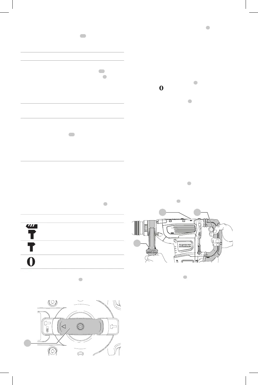
Performing an Application (Fig. A, F)
WARNING: TO REDUCE THE RISK OF PERSONAL
INJURY, ALWAYS ensure workpiece is anchored or
clamped firmly. If drilling thin material, use a wood
“back-up” block to prevent damage to thematerial.
WARNING: Always wait until the motor has come to
a complete standstill before changing the direction
ofrotation.
1. Choose and install the appropriate chuck, adapter, and/
or bit onto to the tool. Refer to Bit and BitHolder.
2. Using the mode selector dial
4
, selectthe mode
appropriate to desired application. Refer to
OperationModes.
3. Adjust the side handle
2
asnecessary.
Fig. F
2
4 1
4. Place the bit/chisel on the desiredlocation.
5. Depress the trigger switch
1
.
6. To stop the hammer, release theswitch.
Recommendations for Tool Operation
• Large (7,9 mm to 12,7 mm [ 5/16" to 1/2"]) holes in
steel can be made easier if a pilot hole (4 mm to 4,8 mm
[5/32" to 3/16"]) is drilledfirst.
• When drilling, always apply pressure in a straight line
with the bit, but do not push hard enough to stall the
motor or deflect thebit. A smooth even flow of material
indicates the proper drillingrate.
• If drilling thin material or material that is prone to
splinter, use a wood “back-up” block to prevent damage
to theworkpiece.
 Loading...