ENGLISH
23
WARNING: Do not attempt to tighten or loosen drill
bits (or any other accessory) by gripping the front part
of the chuck and turning the tool on. Damage to the
chuck and personal injury mayoccur.
The rotary hammer can be fitted with various chisel bits
depending on the desired application. Use sharp drill
bitsonly.
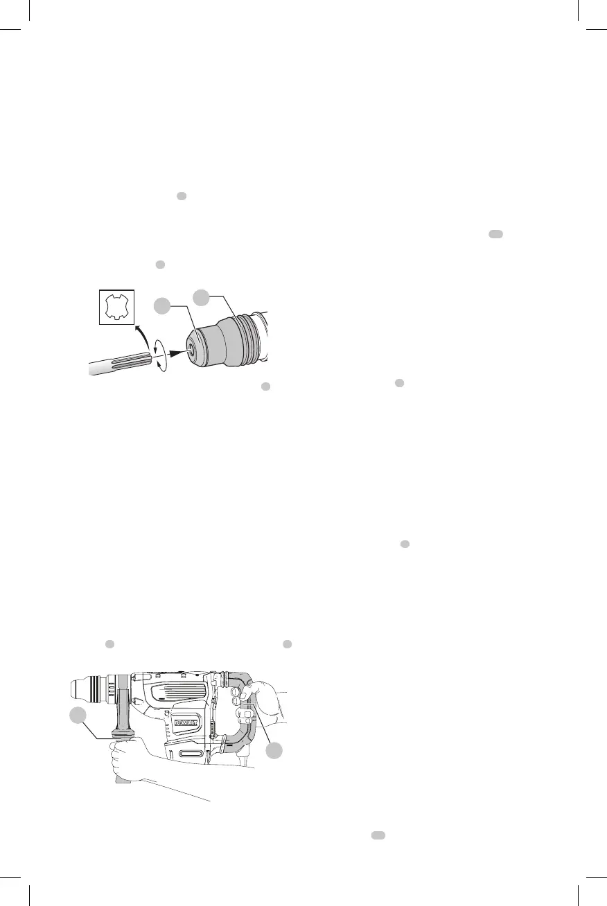
Inserting and Removing SDS MAX Bits
(Fig. C)
1. Insert bit in the bit holder
6
and apply downward
pressure while rotating to secure the bit into place. The
bit shank must beclean.
2. Ensure the bit is properlyengaged.
NOTE: The bit needs to move several centimeters in and
out of the bit holder
6
when properlyengaged.
6
7
Fig. C
3. To remove the bit, pull back the locking sleeve
7
and
pull the bitout.
OPERATION
WARNING: Always observe the safety instructions
and applicableregulations.
WARNING: To reduce the risk of serious personal
injury, turn unit off and disconnect it from
power source before making any adjustments or
removing/installing attachments or accessories.
An accidental start-up can causeinjury.
Proper Hand Position (Fig. D)
WARNING: To reduce the risk of serious personal injury,
ALWAYS use proper hand position as shown.
WARNING: To reduce the risk of serious personal
injury, ALWAYS hold securely in anticipation of a
suddenreaction.
Proper hand position requires one hand on the mounted
side handle
2
, with the other hand on the mainhandle
5
.
Fig. D
2
5
SHOCKS Active Vibration Control®
System
For best vibration control, hold the tool as described in
Proper Hand Position and apply just enough pressure so
the damping device on the main handle is approximately
mid stroke. The hammer only needs enough pressure to
engage the active vibration control. Applying too much
pressure will not make the tool actuate faster and active
vibration control will notengage.
Tool Tag Ready (Fig. A)
Optional Accessory
Your hammer comes with mounting holes
11
and
fasteners for installing a
Tool Tag. You will need a
T15 bit tip to install the tag. Only use the screws provided.
The
Tool Tag is designed for tracking and locating
professional power tools, equipment, and machines using
the
Tool Connect™ app. For proper installation
and use of the
Tool Tag refer to the
Tool
Tagmanual.
Lock-On Button (Fig. A)
Chipping mode only
The lock-on button
8
offers increased comfort in extended
use applications. To lock the tool on, depress the lock-on
button while the tool is running. The tool will continue to
run after the switch is released. To unlock and turn off the
tool, depress and release theswitch.
NOTE: The lock-on button will not function in drillingmode.
Electronic Speed and Impact Control (Fig. A)
The electronic speed and impact control allows the
use of smaller drill bits without the risk of bit breakage,
hammerdrilling into light and brittle materials without
shattering and optimal tool control for precisechiseling.
To set the speed dial
9
, turn the dial to the desired level.
The higher the number, the greater the speed and impact
energy. Dial settings make the tool extremely flexible and
adaptable for many different appli cations. The required
setting depends on the bit size and hardness of material
beingdrilled.
Overload Clutch
In case of jamming of a drill bit, the drive to the drill spindle
is interrupted by the overload clutch. Due to the resulting
forces, always hold the tool with both hands and take a
firmstance. After the overload, release and depress the
trigger to re-engagedrive.
WARNING: Drill may stall if overloaded causing a
sudden twist. Always expect the stall. Grip the drill
firmly to control the twisting action and avoidinjury.
E-Clutch®
System (Fig. A)
In addition to the integral (mechanical) clutch, the
anti-rotation E-Clutch® system, offers technology capable
of detecting the motion of the tool. This feature senses the
motion of the tool and shuts it down if necessary. The red
indicator LED
10
illuminates when the E-Clutch® System
isengaged.
 Loading...