9
ENGLISH
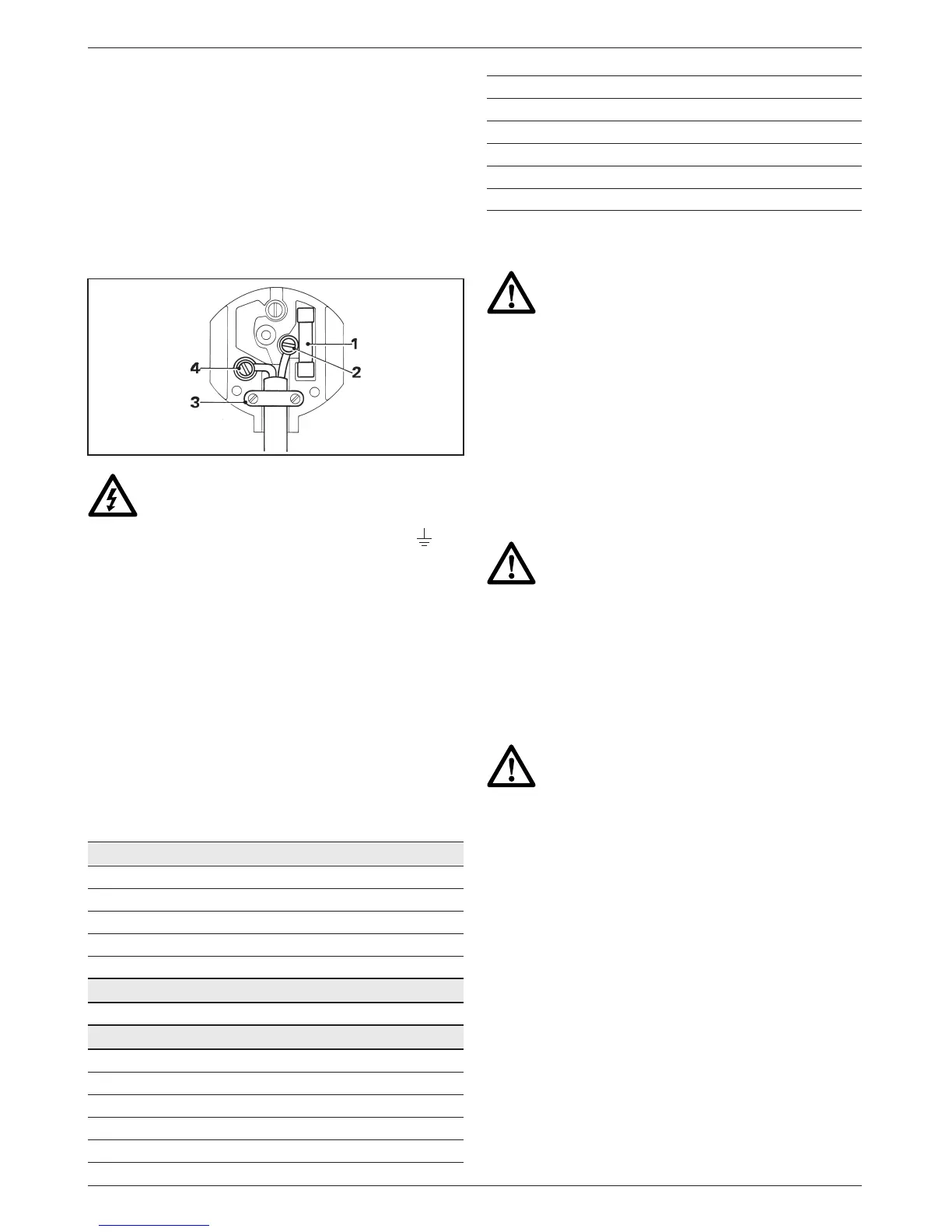
• The cable wire colours, or a letter, will be marked
at the connection points of most good quality
plugs. Attach the wires to their respective points
in the plug (see below). Brown is for Live (L) (2)
and Blue is for Neutral (N) (4).
• Before replacing the top cover of the mains plug
ensure that the cable restraint (3) is holding the
outer sheath of the cable firmly and that the two
leads are correctly fixed at the terminal screws.
Never use a light socket.
Never connect the live (L) or neutral (N)
wires to the earth pin marked E or .
For 115 V units with a power rating exceeding 1500 W,
we recommend to fit a plug to BS4343 standard.
Using an extension cable
If an extension cable is required, use an approved
extension cable suitable for the power input of this
tool (see technical data). The minimum conductor
size is 1.5 mm
2
.
When using a cable reel, always unwind the cable
completely.
Also refer to the table below.
Conductor size (mm
2
) Cable rating (Amperes)
0.75 6
1.00 10
1.50 15
2.50 20
4.00 25
Cable length (m)
7.5 15 25 30 45 60
Voltage Amperes Cable rating (Amperes)
115 0 - 2.0 6 6 6 6 6 10
2.1 - 3.4 6 6 6 6 15 15
3.5 - 5.0 6 6 10 15 20 20
5.1 - 7.0 10 10 15 20 20 25
7.1 - 12.0 15 15 20 25 25 -
12.1 - 20.0 20 20 25 - - -
230 0 - 2.0 6 6 6 6 6 6
2.1 - 3.4 6 6 6 6 6 6
3.5 - 5.0 6 6 6 6 10 15
5.1 - 7.0 10 10 10 10 15 15
7.1 - 12.0 15 15 15 15 20 20
12.1 - 20.0 20 20 20 20 25 -
Assembly
• Prior to assembly always unplug the tool.
• Prior to assembly, check for the
presence of a battery pack and remove it
if present.
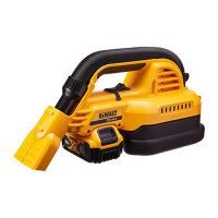
Inserting a battery pack (fig. B)
• Release the latch (12) to open the battery
compartment cover (11).
• Insert the battery pack (13) into the receptacle
(14) until it is fully seated.
• Close the battery compartment cover.
Always switch off the tool before
inserting or removing the battery pack.
Battery pack condition
• Make sure your battery pack is (fully) charged.
If the battery pack does not produce sufficient
power, charge the battery pack following the
instructions in the manual of the charger.
Use only DEWALT battery packs and
chargers.
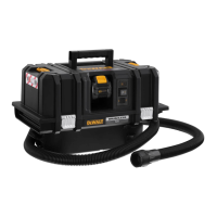
Connecting the hose (fig. C)
Vacuum mode
• Insert the connecting piece (15) into the vacuum
inlet (5).
• Turn the connecting piece clockwise to fix the
hose in position.
• Place the appropriate accessory onto the hose
nozzle (16).
Blow mode
• Insert the connecting piece (15) into the blow
outlet (6).
• Turn the connecting piece clockwise to fix the
hose in position.