ENGLISH
8
ASSEMBLY AND ADJUSTMENTS
WARNING: To reduce the risk of serious personal
injury, turn unit off and remove the battery pack
before making any adjustments or removing/
installing attachments or accessories. An
accidental start‑up can causeinjury.
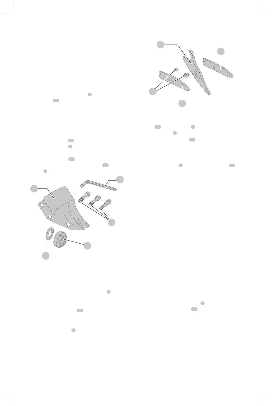
Remove and Replace Parts (Fig. D, E)
Removing the Shear Head Assembly
(Fig. D)
1. To remove shear head assembly
2
from motor, loosen
3 cap screws
10
.
2. Remove shear head assembly by pulling head firmly
forward. Slight twisting action may be required if head
does not slide offeasily.
Removing the Cutter Blades (Fig. D, E)
1. To remove cutter blades from shear head assembly,
remove 3 cap screws
10
from shear housing with the
provided hex wrench
3
. Be careful not to lose rear
spacer bushing when removing middle capscrew.
2. Remove center blade
13
from housing by tapping
blade gently towards the rear. Side knife
12
and side
spacers
9
will now drop out of thehousing.
Fig. D
2
10
11
8
3
Removing and Replacing the Eccentric
Bearing Assembly (Fig. D)
To remove eccentric bearing assembly from shaft, use
an appropriate wrench to loosen eccentric nut
8
by
turningcounterclockwise.
1. To install eccentric bearing assembly onto shaft, make
sure the large thin washer
11
is first inserted overshaft.
2. Screw eccentric bearing assembly onto shaft and
tighten with appropriatewrench.
3. Lubricate eccentric nut
8
with a good grade of
bearinggrease.
Fig. E
9
12
12
13
Installing the Cutter Blades (Fig. D, E)
1. To install cutter blades into shear housing, place the side
knife
12
and side spacer
9
into position in the shear
head assembly
2
.
2. Insert center cap screws
10
through side knife and side
spacer with rear spacer bushing betweenthem.
3. Start cap screw into thread just enough to hold blades
in place. DO NOTTIGHTEN.
4. Insert side spacers
9
into hole in center blade
13
andlubricate.
5. Install center blade into shear housing by tapping blade
gently forward using a drift to line up hole in center
blade with forward holes in housing. Insert and tighten
forward cap screw making sure spacer bushing in center
blade stays inposition.
6. Apply good grade of bearing grease to clevis or yoke
in center blade where it rides on the eccentric bearing
assembly. Insert rear cap screw into shear housing but
do not completelytighten.
NOTE: Change the side knives after they show a width wear
pattern of 50%. Swap the knives left to right and use them
until the patterns meet. When the patterns meet, invert the
left and right side knives and use them until they show a
width wear pattern of 50%. They can then be swapped from
left to right until you use all 4 sides of the blades. Never
exceed 10000 feet of cutting on a set of side knives. The tool
will continue to cut after these landmarks are reached, but
the power unit will becomeoverloaded.
Installing the Shear Head Assembly
(Fig. D)
1. To install shear head assembly
2
onto drive motor,
make sure all cap screws
10
are loosened about 3 or 4
completeturns.
2. Place shear head onto unit and alternately tighten cap
screws snugly to lock head assembly in place. It may be
necessary to gently tap the shear head into place if it
does not readily slip onto the nose of the powerunit.
3. Tighten all three cap screws to 45–50 in‑lbs.
(5.08‑5.64Nm). Failure to tighten the cap screws
properly can cause the cap screws tobreak.