If
by any
chance
the
blade
does
not lie
flat against
the
fence then return
it to the 0°
cross-cut position
and
repeat
the
above adjustment procedure (making
blade parallel
to arm
tracks).
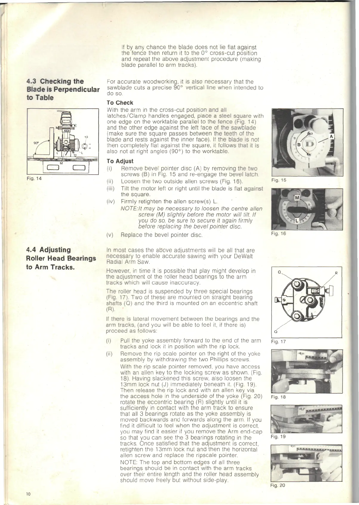
4.3
Checking
the
Blade
is
Perpendicular
to
Table
Fig.
14
4.4
Adjusting
Roller
Head
Bearings
to Arm
Tracks.
(iv)
For
accurate woodworking,
it is
also necessary that
the
sawblade cuts
a
precise
90°
vertical
line
when
intended
to
do so.
To
Check
With
the arm in the
cross-cut position
and all
latches/Clamp handles engaged, place
a
steel square with
one
edge
on the
worktable parallel
to the
fence (Fig.
14)
and the
other edge against
the
left
face
of the
sawblade
(make sure
the
square passes between
the
teeth
of the
blade
and
rests against
the
inner face).
If the
blade
is not
then completely flat against
the
square,
it
follows
that
it is
also
not at
right angles (90°)
to the
worktable.
To
Adjust
(i)
Remove bevel pointer disc
(A) by
removing
the two
screws
(B) in
Fig.
15
and
re-engage
the
bevel
latch.
Loosen
the two
outside
alien
screws
(Fig.
16).
Tilt
the
motor
left
or
right
until
the
blade
is
flat
against
the
square.
Firmly
retighten
the
alien
screw(s)
L.
NOTE:It
may be
necessary
to
loosen
the
centre
alien
screw
(M)
slightly before
the
motor
will
tilt.
If
you do so, be
sure
to
secure
it
again
firmly
before replacing
the
bevel pointer disc.
(v)
Replace
the
bevel pointer disc.
In
most cases
the
above adjustments will
be all
that
are
necessary
to
enable accurate
sawing
with
your
DeWalt
Radial
Arm
Saw.
However,
in
time
it is
possible that play might develop
in
the
adjustment
of the
roller
head
bearings
to the arm
tracks
which
will
cause inaccuracy.
The
roller head
is
suspended
by
three special bearings
(Fig.
17).
Two of
these
are
mounted
on
straight bearing
shafts
(Q) and the
third
is
mounted
on an
eccentric shaft
(R).
If
there
is
lateral movement between
the
bearings
and the
arm
tracks, (and
you
will
be
able
to
feel
it, if
there
is)
proceed
as
follows:
(i)
Pull
the
yoke assembly forward
to the end of the arm
tracks
and
lock
it in
position with
the rip
lock.
(ii) Remove
the rip
scale
pointer
on the
right
of the
yoke
assembly
by
withdrawing
the two
Phillips screws.
With
the rip
scale pointer removed,
you
have access
with
an
alien
key to the
locking
screw
as
shown. (Fig.
18).
Having slackened this screw, also loosen
the
13mm
lock
nut (J)
immediately beneath
it.
(Fig. 19).
Then
release
the rip
lock
and
with
an
alien
key via
the
access hole
in the
underside
of the
yoke (Fig.
20)
rotate
the
eccentric bearing
(R)
slightly until
it is
sufficiently
in
contact with
the arm
track
to
ensure
that
all 3
bearings rotate
as the
yoke assembly
is
moved backwards
and
forwards along
the
arm.
If you
find
it
difficult
to
feel when
the
adjustment
is
correct,
you
may
find
it
easier
if you
remove
the Arm
end-cap
so
that
you can see the 3
bearings rotating
in the
tracks.
Once satisfied that
the
adjustment
is
correct,
retighten
the
13mm
lock
nut and
then
the
horizontal
alien screw
and
replace
the
ripscale pointer.
NOTE:
The top and
bottom edges
of all
three
bearings
should
be in
contact
with
the arm
tracks
over
their
entire length
and the
roller
head assembly
should move freely
but
without side-play.
Fig.
15
Fig.
16
Fig.
17
Fig.
18
Fig.
19
Fig.
20
10