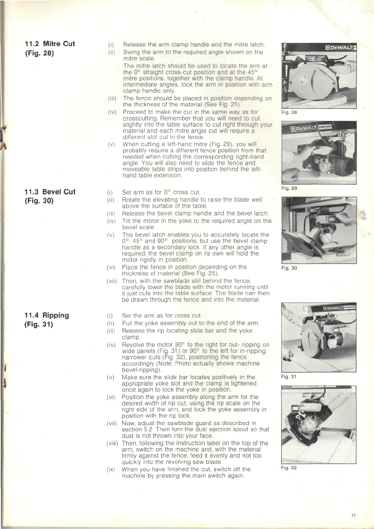
11.2
Mitre
Cut
(Fig.
28)
(v)
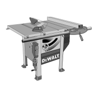
11.3
Bevel
Cut
(Fig.
30)
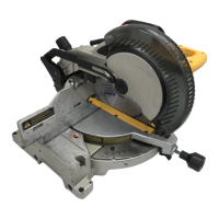
11.4 Ripping
(Fig.
31)
(v)
(viii)
IX
Release
the arm
clamp
handle
and the
mitre
latch.
Swing
the arm to the
required angle shown
on the
mitre scale.
The
mitre
latch
should
be
used
to
locate
the arm at
the
0°
straight cross-cut position
and at the 45°
mitre
positions, together with
the
clamp
handle.
At
intermediate angles, lock
the arm in
position
with
arm
clamp handle only.
The
fence should
be
placed
in
position
depending
on
the
thickness
of the
material (See Fig. 25).
Proceed
to
make
the cut in the
same
way as for
crosscutting. Remember that
you
will need
to cut
slightly
into
the
table surface
to cut
right through
your
material
and
each
mitre angle
cut
will require
a
different
slot
cut in the
fence.
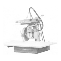
When cutting
a
left-hand mitre (Fig. 29),
you
will
probably require
a
different
fence position from that
needed when cutting
the
corresponding right-hand
angle.
You
will also need
to
slide
the
fence
and
moveable table strips into position behind
the
left-
hand table extension.
Set
arm as for 0°
cross cut.
Rotate
the
elevating handle
to
raise
the
blade well
above
the
surface
of the
table.
Release
the
bevel
clamp
handle
and the
bevel latch.
Tilt
the
motor
in the
yoke
to the
required
angle
on the
bevel scale.
The
bevel latch enables
you to
accurately locate
the
0°,
45° and 90°
positions,
but use the
bevel clamp
handle
as a
secondary lock.
If any
other angle
is
required,
the
bevel
clamp
on its own
will hold
the
motor rigidly
in
position.
Place
the
fence
in
position depending
on the
thickness
of
material (See Fig. 25).
Then, with
the
sawblade still behind
the
fence,
carefully
lower
the
blade
with
the
motor running until
it
just cuts into
the
table surface.
The
blade
can
then
be
drawn through
the
fence
and
into
the
material.
Set
the arm as for
cross cut.
Pull
the
yoke assembly
out to the end of the
arm.
Release
the rip
locating slide
bar and the
yoke
clamp.
Revolve
the
motor
90° to the
right
for
out- ripping
on
wide
panels (Fig.
31)
or 90° to the
left
for
in-ripping
narrower
cuts (Fig. 32), positioning
the
fence
accordingly (Note: Photo actually shows machine
bevel-ripping).
Make sure
the
slide
bar
locates positively
in the
appropriate
yoke slot
and the
clamp
is
tightened
once
again
to
lock
the
yoke
in
position.
Position
the
yoke assembly along
the arm for the
desired width
of rip
cut. using
the rip
scale
on the
right
side
of the
arm,
and
lock
the
yoke assembly
in
position
with
the rip
lock.
Now,
adjust
the
sawblade guard
as
described
in
section 5.2. Then turn
the
dust ejection spout
so
that
dust
is not
thrown into your face.
Then, following
the
instruction label
on the top of the
arm, switch
on the
machine and, with
the
material
firmly
against
the
fence,
feed
it
evenly
and not too
quickly
into
the
revolving
saw
blade.
When
you
have finished
the
cut, switch
off the
machine
by
pressing
the
main switch again.
Fig.
28
Fig.
29
Fig.
30
Fig.
31
Fig.
32
17