12.7 Routing
Fig.
61
Fig.
62
J
\
Fig.
65
•J
\
^-
J
Fig.
66
The
mounting
of one of the
optional Router Brackets,
enabling
you to fit a
portable Router
to
your
Powershop,
broadens
the
scope
enormously
for
accurate,
decorative
woodworking
with your machine.
There
is a
choice
of two
mounting brackets:-
One is
suitable
for the
Black
&
Decker
DN66
Woodworker
or
any
other
with
a.043mm
collar.
The
other
will
enable
most
ELU
Routers (MOF 96/31
/98/77)
to be
secured
to
your
Powershop.
Since
the
Router itself
will
be
operating
and not the
Powershop
motor,
you can
disconnect
the
Powershop
completely
from
the
power supply.
The
mounting procedure
is as
follows:-
(i)
Remove
the
blade guard, blade
and all
flanges from
the
motor shaft.
(ii) Position
the
router bracket over
the end of the
Powershop motor
shaft,
carefully locating
the
lugs
of
the
bracket
behind
the
lugs
on the end of the
machine's motor housing (Fig. 59).
In
lining these
up
correctly,
the
hole
in the
upper
arm of the
bracket
will
also locate over
the
standard guard retaining
bolt
on
the top of the
motor housing, where
it can be
firmly
secured with
the
wing
nut
supplied,
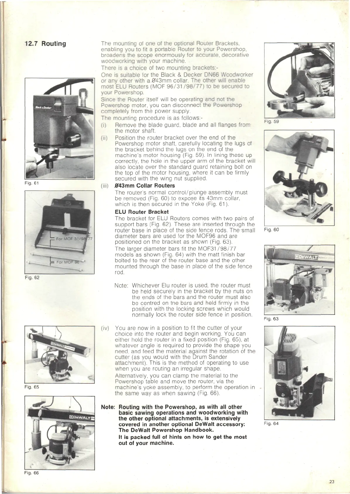
(iii)
j043mm
Collar Routers
The
router's
normal
control/plunge
assembly
must
be
removed (Fig.
60) to
expose
its
43mm collar,
which
is
then secured
in the
Yoke (Fig.
61).
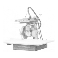
ELU
Router Bracket
The
bracket
for ELU
Routers comes with
two
pairs
of
support
bars (Fig. 62). These
are
inserted through
the
router
base
in
place
of the
side fence rods.
The-small
diameter bars
are
used
for the
MOF96
and are
positioned
on the
bracket
as
shown (Fig. 63).
The
larger diameter bars
fit the
MOF31
/98/77
models
as
shown (Fig.
64)
with
the
matt finish
bar
bolted
to the
rear
of the
router base
and the
other
mounted through
the
base
in
place
of the
side fence
rod.
Note: Whichever
Elu
router
is
used,
the
router must
be
held securely
in the
bracket
by the
nuts
on
the
ends
of the
bars
and the
router must also
be
centred
on tne
bars
and
held firmly
in the
position with
the
locking screws which would
normally
lock
the
router side fence
in
position.
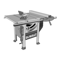
(iv)
You are now in a
position
to fit the
cutter
of
your
choice into
the
router
and
begin working.
You can
either hold
the
router
in a
fixed position (Fig. 65),
at
whatever
angle
is
required
to
provide
the
shape
you
need,
and
feed
the
material against
the
rotation
of the
cutter
(as you
would with
the
Drum Sander
attachment). This
is the
method
of
operating
to use
when
you are
routing
an
irregular shape.
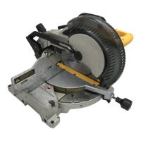
Alternatively,
you can
clamp
the
material
to the
Powershop table
and
move
the
router,
via the
machine's yoke assembly,
to
perform
the
operation
in
the
same
way as
when sawing (Fig. 66).
Note: Routing with
the
Powershop,
as
with
all
other
basic sawing operations
and
woodworking with
the
other optional attachments,
is
extensively
covered
in
another optional DeWalt accessory:
The
DeWalt Powershop Handbook.
It
is
packed full
of
hints
on how to get the
most
out of
your machine.
Fig.
60
Fig.
63
Fig.
64
23