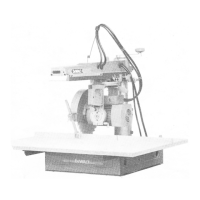
3.
ASSEMBLY
OF
WORKTABLE
ONTO
SUPPORT
BRACKETS
Note:
The
worktable comprises
5
elements (Fig.
5):
a
large fixed
portion
(F)
which attaches
to
the
front
of
the
base
frame,
a
wooden fence
(M)
against which
the
material being worked
is
held
and
three movable strips
of
table which
are
used
to
adjust
the
position
of the
fence
relative
to the saw
blade
to
ensure
the
different
types/depth
of cut can be
carried
out
with safety.
(i)
Secure
the
front board
(F) to the
support
brackets
using
the
slotheaded bolts
(G) and the
relative
washers
and
nuts making sure that
the
holes
in the
middle
of the
board locate over
the
central support
flange
in the
base frame.
Note:
The
additional holes
on the
left
hand side
of the
table
are for
mounting
the
table side extension.
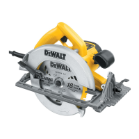
(ii)
Mount
the
sawblade (see
Fig.6)
making sure
the
lower
teeth point towards
the
back
of the
machine.
Tighten
the
blade
on the
shaft
using
the
larger
of the
alien keys provided
to
hold
the
shaft steady
while
tightening
the
arbor
nut
anti-clockwise (left-hand
thread)
with
the
large open-ended spanner.
(Note
that
the
brass arbor
nut has an
inner circular ring
rather
than being hexagonal across
its
full
width
- the nut
should always
be
mounted with this inner ring facing
the
motor).
(iii)
You can now
check that
the
front board
is
flat
and
parallel
to the arm
across
its
entire
width.
To do
this,
lower
the
blade
so
that
the
bottom tooth just touches
the
front
board
on the
front
left
hand side. Then, with
the
mitre latch
and
clamp released, swing
the arm so
that
the
blade skims
the top of the
board across
its
width.
If the tip of the
blade,
does
not
just
touch
the
board
all the way
across, then with
a
screwdriver
adjust
the
front adjusting screw
in the
middle
of the
board
up or
down until that
is the
case. Then move
the
sawblade back along
the arm and
adjust
the
rear
adjusting
screw
in the
same way.
(iv)
Mount
the
blade guard
as
follows:-
1.
Release
the
bevel latch
(14)
and
bevel clamp (12)
and
tilt
the
motor
and
blade about
30° to the
left.
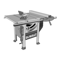
2.
Loosen
the
locking screw
(P)
(Fig.
7) and
turn
the
retaining
bracket
(N)
anti-clockwise until
the
right
hook
of the
rear
black guard
(F) can be
lifted
free
of
the
support lug.
3.
Slide
the
black guard round clockwise until
it
reaches
the
dotted line position
in
the
illustration.
4.
Now
lower
the
guard over
the
sawblade making sure
that
the
hinged plastic section does
not
foul
against
the
motor shaft
and
that
the
lower metal edge
on the
other
side
of the
guard engages satisfactorily with
the
lugs
on the
motor housing
-
this will ensure also that
the
hole
on the
upper guard bracket locates over
the
retention bolt
on top of the
motor.
Place
the
washer
on the
bolt
and
secure
the
wing
nut
to
hold
the
guard
firmly.
NOTE:Whenever
you
remove
the
guard,
resecure
the
wing
nut and its
washer
to the
retaining bolt
on
top of the
motor
housing
so
that
no
parts
can
be
lost.
ALWAYS
REPLACE
THE
GUARD BEFORE
SWITCHING
ON
YOUR MACHINE
AND
REMEMBER
THAT EVEN
A
STATIONARY
SAWBLADE
IS
SHARP
SO
TAKE CARE
NOT
TO
CATCH YOURSELF
ON THE
TEETH.
6.
Slide
the
black
guard
(F)
back round anti-clockwise
and
hook
the
right-hand
end of it
onto
the
support
lug,
then
secure bracket
(N)
over
the
same
lug by
tightening
screw (P).
Fig.
5
-
f
'
i
«t
I
Fig.
6
Fig.
7